In-vehicle device cooling apparatus

a technology for cooling apparatus and in-vehicle device, which is applied in the direction of cell components, cell components, propulsion by batteries/cells, etc., can solve the problem of not being able to appropriately respond to a cooling request from one of the battery modules and the electric components

Inactive Publication Date: 2011-03-08
TOYOTA JIDOSHA KK
View PDF25 Cites 49 Cited by
  • Summary
  • Abstract
  • Description
  • Claims
  • Application Information

AI Technical Summary

Benefits of technology

[0009]The present invention has been made to solve the above-described problem, and an object thereof is to provide a cooling apparatus that can precisely cool a power storage mechanism, e.g., a secondary battery, and an electric device, which are in-vehicle devices.
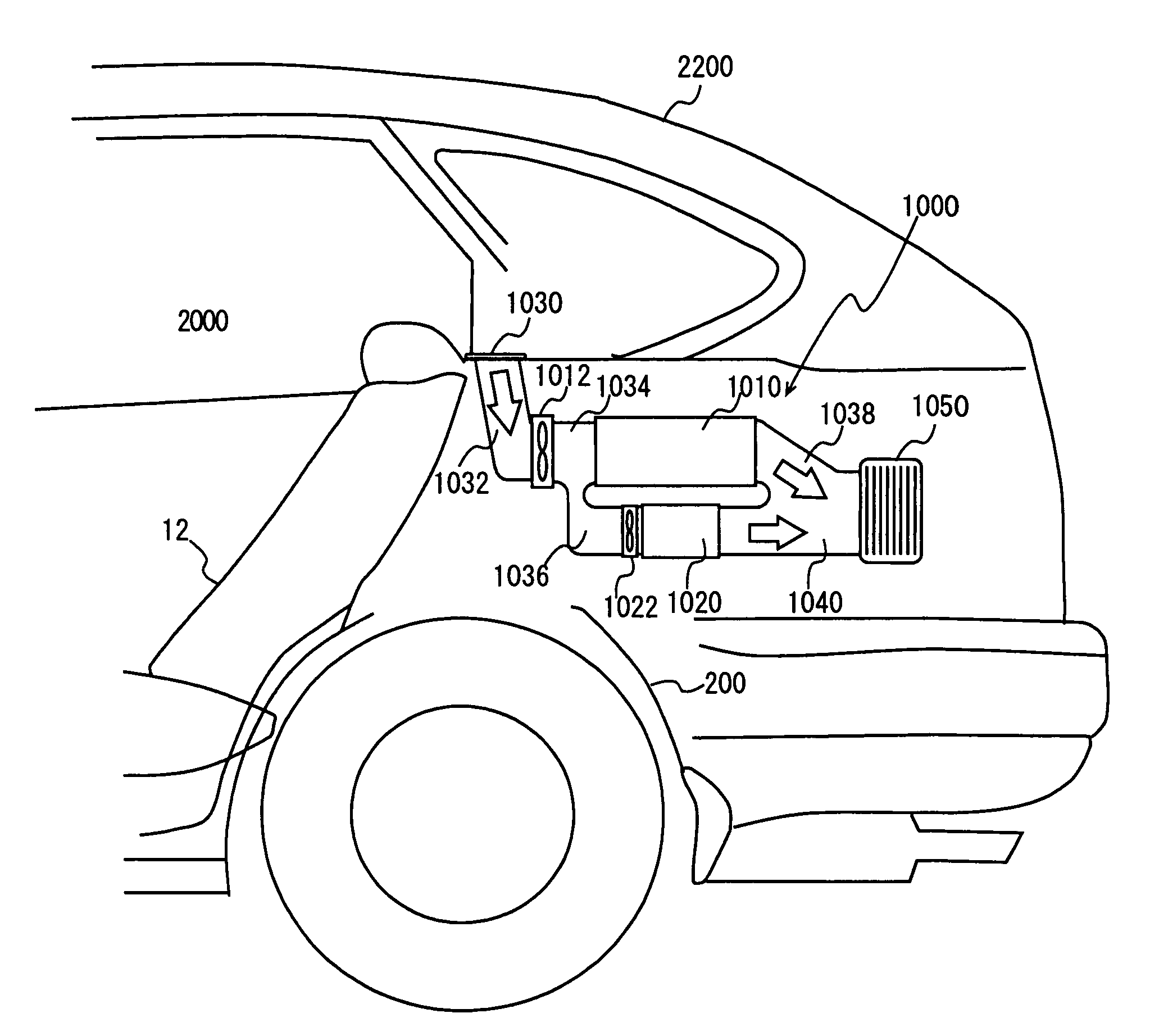
[0011]According to the present invention, one of the first and second supply passages is configured to branch from the other at the branching portion on the upstream side of the power storage mechanism and the electric device. Therefore, the supply passages can be shared and the size of the cooling apparatus can be suppressed. Furthermore, for example at the branching portion, the adjustment mechanism adjusting the flow rate of the medium flowing through the first (or second) supply passage is installed. As the adjustment mechanism adjusts the flow rate of the medium in accordance with a cooling request of the power storage mechanism and that of the electric device, the one having the greater cooling request than the other can be supplied with the greater medium. As a result, the cooling apparatus that can precisely cool the power storage mechanism and an electric device, which are the in-vehicle devices, can be provided.
[0015]According to the present invention, a pump (for a liquid medium) or a fan (for a gas medium) is installed upstream from the branching portion as the first medium supply mechanism. Further, an additional second medium supply mechanism is installed in one of the supply passages downstream from the branching portion. By the control unit controlling the medium supply mechanisms in accordance with the cooling requests of the power storage mechanism and the electric device so that one of or both of the two medium supply mechanisms is / are operated, the power storage mechanism and the electric device can appropriately be cooled. As a result, the cooling apparatus that can precisely cool the power storage mechanism and an electric device, which are the in-vehicle devices, can be provided.
[0017]According to the present invention, it is configured such that one of the first and second supply passages merges into the other at the merging portion on the downstream side of the power storage mechanism and the electric device. Therefore, the supply passages can be shared and the size of the cooling apparatus can be suppressed. Furthermore, for example at the merging portion, the adjustment mechanism adjusting the flow rate of the medium flowing through the first (or second) supply passage is installed. As the adjustment mechanism adjusts the flow rate of the medium in accordance with a cooling request of the power storage mechanism and that of the electric device, the one having the greater cooling request than the other can be supplied with the greater medium. As a result, the cooling apparatus that can precisely cool the power storage mechanism and an electric device, which are the in-vehicle devices, can be provided.
[0021]According to the present invention, a pump (for a liquid medium) or a fan (for a gas medium) is installed downstream from the merging portion as the first medium supply mechanism. Further, the additional second medium supply mechanism is installed in one of the supply passages upstream from the merging portion. By the control unit controlling the medium supply mechanisms in accordance with the cooling requests of the power storage mechanism and the electric device so that one of or both of the two medium supply mechanisms is / are operated, the power storage mechanism and the electric device can appropriately be cooled. As a result, the cooling apparatus that can precisely cool the power storage mechanism and an electric device, which are the in-vehicle devices, can be provided.
[0023]According to the present invention, the second medium supply mechanism is installed in the supply passage where the device having the greater cooling request than the other is installed, and that supply passage is supplied with the medium by the two medium supply mechanisms arranged in series. Accordingly, the device having the greater cooling request can be cooled more strongly.

Problems solved by technology

Accordingly, even though the battery pack including the cooling fan (and the battery module and the electric components) may be reduced in size, it is not possible to appropriately respond to a cooling request from one of the battery module and the electric components.

Method used


Image

  • In-vehicle device cooling apparatus
  • In-vehicle device cooling apparatus
  • In-vehicle device cooling apparatus

Examples


Embodiment Construction

[0041]In the following, referring to the drawings, an embodiment of the present invention will be described. In the following description, the same components are denoted by the same reference characters. Their name and function are also the same. Accordingly, detailed description thereof will not be repeated.

[0042]Referring to FIGS. 1 and 2, a vehicle 10 in which a cooling apparatus for a drive-purpose power supply unit 20 is employed is described. Drive-purpose power supply unit 20 is constituted of a power storage mechanism and an associated electric device. The power storage mechanism may be a secondary battery (hereinafter also referred to as a battery), and also may be fuel cells, a capacitor or the like. When the power storage mechanism is a battery, it may be any of a lead-acid battery, a lithium-ion battery, and a nickel-hydride battery, or it may be any other battery. The associated electric device is an electric device such as an inverter or a DC / DC converter, which must ...


PUM

PropertyMeasurementUnit
output voltageaaaaaaaaaa
rated voltageaaaaaaaaaa

Abstract

A cooling apparatus cools a battery and a DC / DC converter. In a duct, a battery cooling fan having a great rated capacity is installed. The duct branches into a battery-side intake duct and a DC / DC converter-side intake duct on the downstream side of the battery cooling fan. In the battery-side intake duct, the battery is installed to received cooling air. In the DC / DC converter side intake duct, the DC / DC converter is installed to receive cooling air. A DC / DC converter cooling fan having a small rated capacity is installed directly upstream of the DC / DC converter. An ECU controls the two cooling fans based on the temperature of the battery and the DC / DC converter.

Description

[0001]This is a 371 national phase application of PCT / JP2006 / 319233 filed 21 Sep. 2006, claiming priority to Japanese Patent Application No. 2005-293655 filed 6 Oct. 2005, the contents of which are incorporated herein by reference.TECHNICAL FIELD[0002]The present invention relates to a cooling apparatus for an in-vehicle device, and particularly, to a cooling apparatus for an in-vehicle device that can cool the device appropriately.BACKGROUND ART[0003]A vehicle incorporating powertrain referred to as a hybrid system has been developed and put into practical use. The hybrid system is a combination of an internal combustion engine (for example, a known engine such as a gasoline engine, a diesel engine or the like may be used) and an electric motor. Such a vehicle incorporates electric devices such as a secondary battery for driving an electric motor for traveling purpose, an inverter, a DC / DC converter and the like. The secondary battery is discharged and charged by a chemical reactio...

Claims


Application Information

Patent Timeline
Patent Type & Authority Patents(United States)
IPC IPC(8): B60K11/00B60K11/06B60L15/00H01M50/202
CPCB60K1/04B60K2001/005B60L2210/10B60L2240/525B60L2260/56H01M10/625H01M10/633H01M10/647H01M10/6556H01M10/667H01M10/6566H01M10/613B60L50/64Y02T10/72Y02T10/70Y02E60/10H01M50/202B60K11/06B60L15/00
Inventor SHINMURA, OSAMU
Owner TOYOTA JIDOSHA KK
Why Eureka
Try Eureka