Terminal refrigeration system with refrigerant pump and data center terminal refrigeration system

A refrigeration system and refrigerant pump technology, applied in refrigeration and liquefaction, refrigerators, refrigeration components, etc., can solve problems such as inability to meet data center power density, long data center cooling solution cycles, and difficulty in air conditioning stability and reliability. , to achieve the effect of expanding deployment methods and flexibility, facilitating online expansion, and reducing operating costs

Inactive Publication Date: 2013-05-01
SHENZHEN SMART CUBIC INTELLIGENT TECH CO LTD
View PDF5 Cites 12 Cited by
  • Summary
  • Abstract
  • Description
  • Claims
  • Application Information

AI Technical Summary

Problems solved by technology

[0005] 1. The relative distance between indoor and outdoor units of traditional air-cooled machine room air conditioners and the relative installation drop limit affect the deployment of cooling solutions;
[0006] 2. The stability and reliability of air conditioners in traditional small and medium computer rooms have always been a difficult problem in the industry. So far, no good solution has been obtained. At the same time, when there are many small and medium computer room air conditioners in the computer room, its maintenance, Maintenance work also requires considerable costs;
[0007] 3. With the increase of the power density of the computer room, the space in the data center is occupied by more and more computer room air conditioners, and the power consumption of the computer room air conditioner becomes astonishing;
[0008] 4. The construction and deployment period of traditional data center cooling solutions is too long, and the low efficiency of large-space air supply cooling methods has become more and more criticized
The efficiency and cooling capacity of large-scale chillers have relatively large advantages, but the use of chilled water as a cooling source also brings water hazards to the data center, which is also a hidden worry that has always existed in water-cooled air-conditioning systems
At the same time, the use of water-cooled air-conditioning systems and cooling methods near heat sources still cannot meet the increasing power density requirements of modern data centers

Method used


Image

  • Terminal refrigeration system with refrigerant pump and data center terminal refrigeration system

Examples


Embodiment Construction

[0033] In order to make the object, technical solution and advantages of the present invention clearer, the present invention will be further described in detail below in conjunction with the accompanying drawings and embodiments. It should be understood that the specific embodiments described here are only used to explain the present invention, not to limit the present invention.

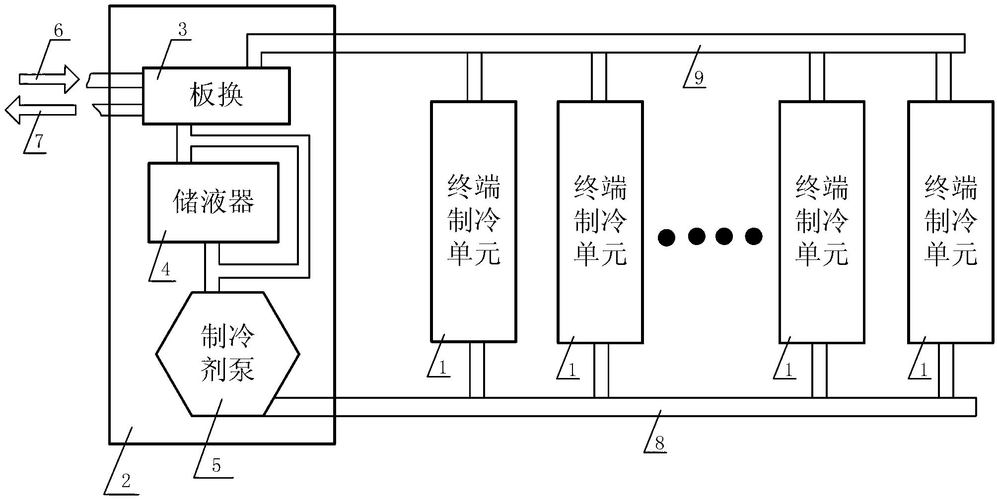
[0034] Such as figure 1 As shown, a terminal refrigeration system with a refrigerant pump includes a number of dispersed terminal refrigeration units 1, wherein the number of terminal refrigeration units 1 can be flexibly deployed according to actual needs, refrigeration distribution units 2, refrigerant pipelines , refrigerant inlet 6, refrigerant outlet 7; the refrigeration distribution unit 2 is connected to the terminal refrigeration unit 1 through a refrigerant pipeline, and the refrigeration distribution unit 2 is used to provide cycle power and refrigeration for the terminal refrigeration sy...


PUM


Abstract

The invention is applicable to the field of refrigeration and provides a terminal refrigeration system with a refrigerant pump. The terminal refrigeration system with the refrigerant pump is characterized in that the terminal refrigeration system comprises a plurality of scattered terminal refrigeration units, a refrigeration distribution unit, a refrigerant pipeline, a refrigerant inlet and a refrigerant outlet, wherein the refrigeration distribution unit is connected with the terminal refrigeration units through the refrigerant pipeline, the refrigeration distribution unit is used for providing circulating power and circulating refrigerant for the terminal refrigeration system, and the terminal refrigeration units are used for realizing direct heat exchange between refrigerant and air; and the refrigerant inlet and the refrigerant outlet are connected with the refrigeration distribution unit and are used for providing a cold source to the refrigeration distribution unit. The terminal refrigeration system has the advantages the refrigeration distribution unit and the terminal refrigeration units can be flexibly deployed in a data center machine room and the online expansion is facilitated; and by adopting a near-heat-source refrigeration method, the consumed power for delivering cold air in long distance when a large-space air delivery method is adopted is saved and the energy consumption is reduced.

Description

technical field [0001] The invention belongs to the technical field of refrigeration, in particular to a terminal refrigeration system with a refrigerant pump and a data center terminal refrigeration system. Background technique [0002] In the traditional air-conditioning and refrigeration system, the compressor is the source of all cycle power of the air-conditioning system. The compressor absorbs the low-temperature and low-pressure refrigerant vapor from the evaporator during the system cycle, and discharges the high-temperature and high-pressure refrigerant vapor after supercharging. to the condenser. In the condenser, the high-temperature and high-pressure refrigerant vapor is fully cooled, and finally becomes a liquid refrigerant with relatively low temperature and pressure. The liquid refrigerant coming out of the condenser finally turns into a low-temperature, low-pressure liquid state after being throttled by the throttling mechanism, and finally returns to the ev...

Claims


Application Information

Patent Timeline
Patent Type & Authority Applications(China)
IPC IPC(8): F25B41/00H05K7/20
Inventor 葛海方王维龙朱利伟
Owner SHENZHEN SMART CUBIC INTELLIGENT TECH CO LTD
Why Eureka
Try Eureka