Demodulation circuit for ASK coded or amplitude modulated signals as wells as NFC and RFID devices comprising the same

a demodulation circuit and coded or amplitude modulated (am) technology, applied in the direction of amplitude demodulation, pulse amplitude modulation, pulse technique, etc., can solve the problems of poor efficiency of rectification, complex design of filter for suppressing carrier signals, and implementation of demodulators, so as to improve sensitivity, reduce the effect of filter design and good carrier suppression

Active Publication Date: 2011-03-15
NXP BV
View PDF3 Cites 18 Cited by
  • Summary
  • Abstract
  • Description
  • Claims
  • Application Information

AI Technical Summary

Benefits of technology

[0022]Another advantage of the invention is its good carrier suppression in that theoretically no carrier frequency component at all is left at the output. This eases filter design for the baseband signal treatment stages behind the demodulator.
[0023]Yet another advantage of the present invention is an optimum recovering of baseband signals meaning that the full amplitude information is recovered. Especially for small input signals this allows much higher sensitivity compared to a diode based peak detection demodulator.
[0024]Further, sampling at maximum amplitudes as achieved with the present invention results in relaxed phase noise requirements to clock generation. Mathematically the derivative at the respective maximum of the input signal—which is usually a sine wave signal or close to that—is zero. Therefore, jitter of the sampling clock has only very small influence on the baseband signal.
[0025]Easy and exact signal processing is guaranteed when the signal shaping means are adapted to convert the ASK coded or AM signals into a recovered rectangular clock signal. In order to achieve this by means of simple and cheap components that can easily be implemented in integrated circuits it is suggested to configure the signal shaping means as a limiting amplifier.
[0026]In another embodiment of the invention the signal delay means are integrated in the signal shaping means. This embodiment contributes to reduce the number of components, since it is not longer necessary to design dedicated signal delay means.
[0027]In yet another embodiment of the invention it is suggested to adapt the signal shaping means to variably delay the recovered clock signal according to a delay control signal generated by the amplitude maximum detection means, wherein the delay control signal is indicative for deviations in time of the first sampling points from said amplitude maxima, for increasing or decreasing the delay added to the recovered clock signal in order to adjust the delayed recovered clock signal such that the first sampling points are set to the amplitude maxima of the signal being sampled by the first sampling mixer. With such an embodiment both the signal shaping means and the signal delay means can be controlled by the amplitude maximum detection means, either by the same delay control signal or by independently generated delay control signals.

Problems solved by technology

There are several difficulties in implementing demodulators for such ASK coded or AM signals.
This makes the design of filters for suppressing the carrier signal rather complex.
The disadvantage of this approach is that the rectification has bad efficiency for small carrier amplitudes which limits the operating range.
This known technology typically needs rather complex and power consuming components like a clock source (crystal, PLL) with low phase noise, mixers and a filter.
The known device, however, uses an approach to delay the sampling point by constant delay times to a time point close to the peak of the signal to be sampled, but not exactly to the peak of the signal.

Method used


Image

  • Demodulation circuit for ASK coded or amplitude modulated signals as wells as NFC and RFID devices comprising the same
  • Demodulation circuit for ASK coded or amplitude modulated signals as wells as NFC and RFID devices comprising the same
  • Demodulation circuit for ASK coded or amplitude modulated signals as wells as NFC and RFID devices comprising the same

Examples


Embodiment Construction

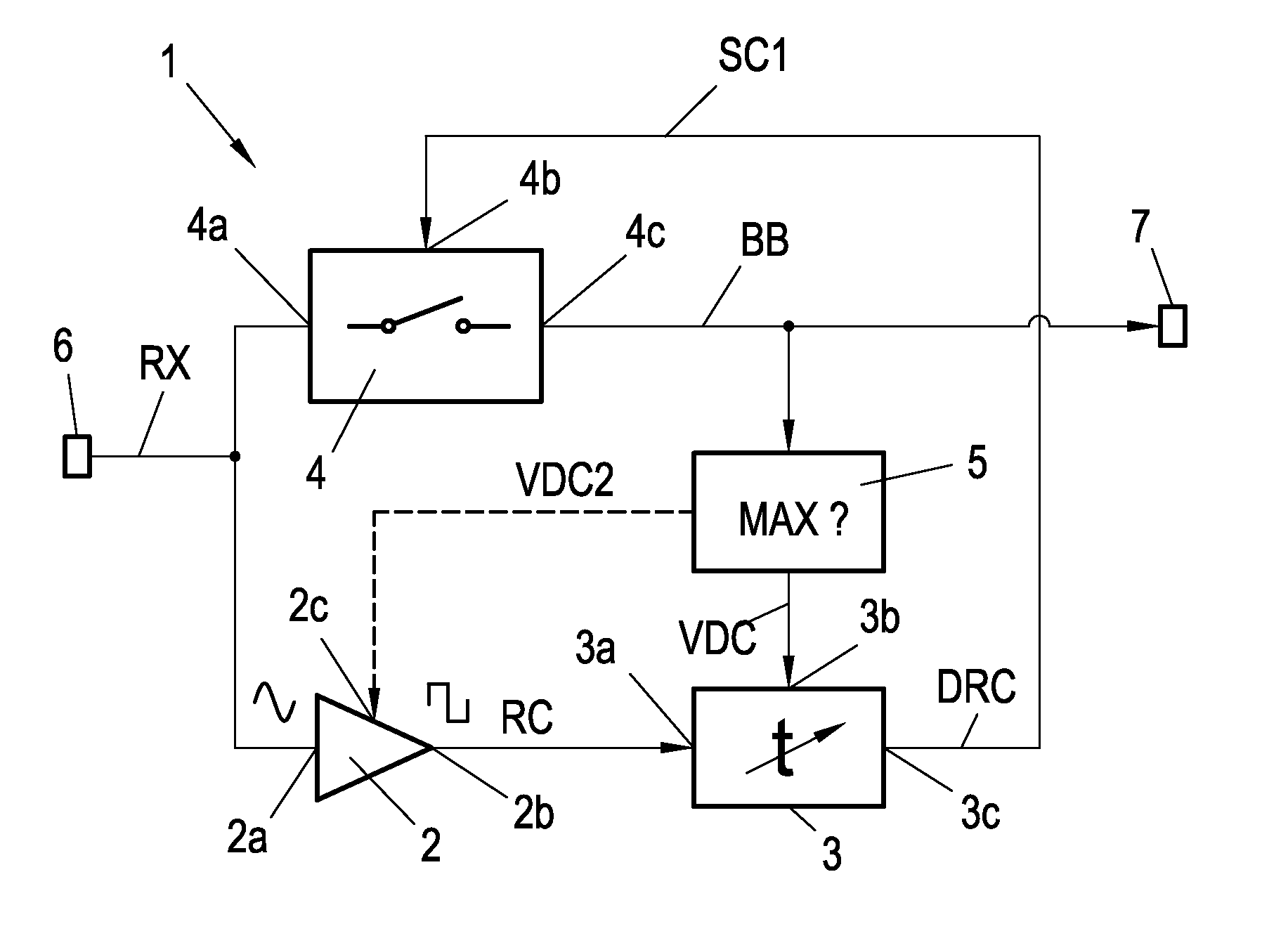
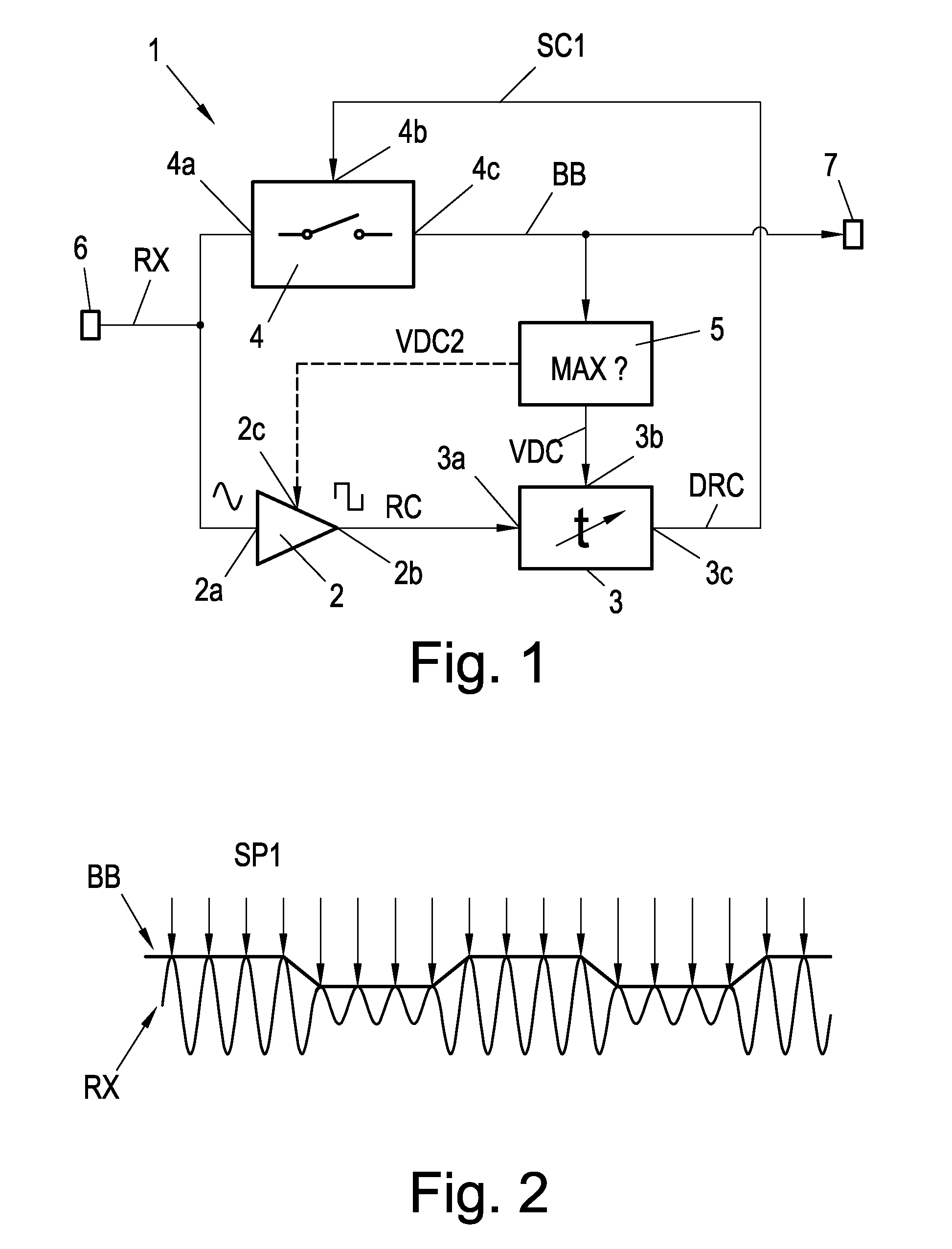
[0044]The basic idea of the demodulation circuit according to the invention is to use a sampling mixer which directly converts the RF signal at a circuit input of the demodulation circuit to the baseband signal of the RF signal, wherein the clock signal needed for this sampling mixer is derived from the RF signal.

[0045]FIG. 1 shows a block circuit diagram of an implementation of the basic function of this invention. The demodulation circuit 1 is adapted to demodulate ASK coded signals RX or amplitude modulated (AM) signals being received at a circuit input 6. It should be observed, that for the sake of simplicity the following description specifically refers to ASK coded signals RX. However, the invention is generally applicable to the demodulation of any form of ASK coded or amplitude modulated (AM) signals. Hence, the term “ASK coded signals RX” used herein is to be understood in a broad sense also comprising amplitude modulated signals. The ASK coded signal RX comprises a carrier...


PUM


Abstract

Conventional modulation envelope demodulators for amplitude modulated signals (e.g. ASK coded signals RX) contain rectifier elements which extract a baseband signal BB. Disadvantageously, due to a non-linear characteristic of the rectifier elements, an amplitude of the baseband signal BB depends on an amplitude of the high-frequent carrier signal. The present invention discloses an improved demodulation circuit for demodulating of ASK coded or amplitude modulated signals. This is achieved by using a sampling mixer 4 and a phase adjusting regulation loop (5) by means of which the sampling of the ASK coded signal RX at its maxima is performed with high accuracy. Due to the absence of any rectifying elements, the baseband signal BB can be fully extracted from the ASK coded signals RX.

Description

FIELD OF THE INVENTION[0001]The invention relates to a demodulation circuit for ASK coded or amplitude modulated (AM) signals comprising a circuit input being adapted to receive an ASK coded or AM signal comprising a carrier signal being ASK coded according to a base band signal or amplitude modulated.[0002]The invention further relates to an NFC device and to an RFID transponder.[0003]The invention is particularly related to Near Field Communication (NFC) devices as described in ISO 18092. For communication between two devices an RF field with 13.56 MHz carrier is used. One device has its transmitter active and generates that field via an antenna while the second device receives the signal through inductive coupling between its own antenna and that of the first device. During communication this RF field is modulated with ASK with a modulation index depending on the current communication mode (see ISO 18092) by the transmitting device. For the receiving device a demodulation method ...

Claims


Application Information

Patent Timeline
Patent Type & Authority Patents(United States)
IPC IPC(8): H03D1/00H03D1/24H03K9/00H03K9/02H03D1/22
CPCH03D1/22H04L27/06
Inventor KRANABENTER, HELMUT
Owner NXP BV
Why Eureka
Try Eureka