Rolling bearing device

a bearing device and rolling bearing technology, applied in the direction of mechanical equipment, rotary machine parts, engine components, etc., can solve the problems of increased production costs and increased noise levels, and achieve the effect of prolonging the life of lubricating oil stored in the tank and prolonging the life of lubricating oil refilled

Inactive Publication Date: 2011-03-22
JTEKT CORP
View PDF14 Cites 12 Cited by
  • Summary
  • Abstract
  • Description
  • Claims
  • Application Information

AI Technical Summary

Benefits of technology

[0021]According to the invention, in the rolling bearing including the nozzle which is inserted between the inner ring and the outer ring of the bearing in such a manner as to be made to open in the annular space defined therebetween and the pump for supplying the lubricating oil stored in the tank via the nozzle, since the groove is formed on the one end face side of the cage which holds the rolling elements at the constant intervals by accommodating them individually in the pockets between the inner ring and the outer ring in such a manner as to extend circumferentially along the full circumference thereof and to communicate individually with the pockets and the nozzle is inserted into the groove so formed at the distal end thereof, the state is produced at the opening at the distal end of the nozzle in which disturbance to airflow and negative pressure are difficult to be produced when compared with the conventional rolling bearing with the self-lubricating function, whereby the lubricating oil supplied from the opening at the distal end of the nozzle is allowed to reach the rolling elements in an ensured fashion for contribution to lubrication of the rolling bearing, and hence, the rolling bearing can efficiently be lubricated by supplying a small amount of lubricating oil. As a result, with an oil supply unit in which a tank cannot be refilled with lubricating oil, the life of lubricating oil stored in the tank can be extended, whereas with an oil supply unit in which a tank can be refilled with lubricating oil, an interval at which lubricating oil is refilled can be extended.

Problems solved by technology

This causes problems that the production costs are increased and that the noise level is increased due to the use of compressed air.

Method used


Image

  • Rolling bearing device
  • Rolling bearing device
  • Rolling bearing device

Examples


Embodiment Construction

[0034]Hereinafter, embodiments of the invention will be described by reference to the drawings.

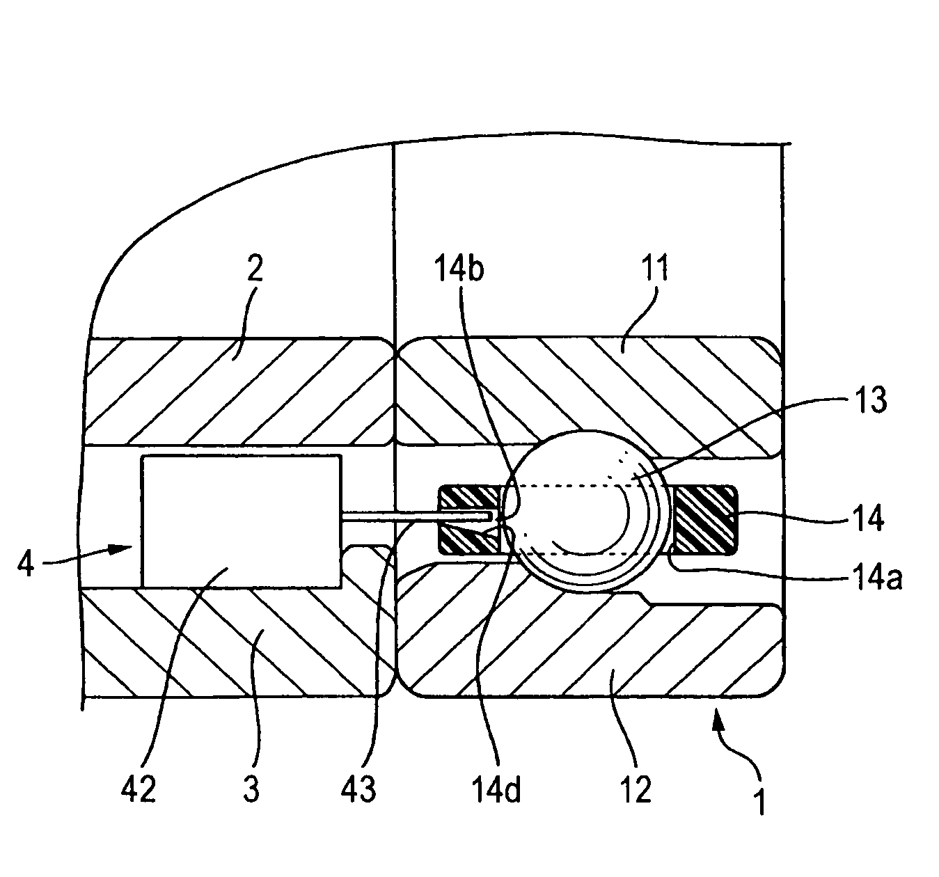
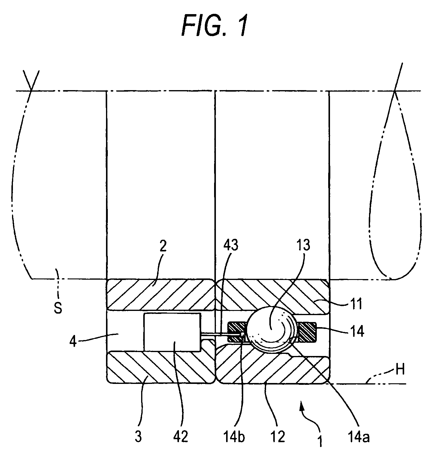
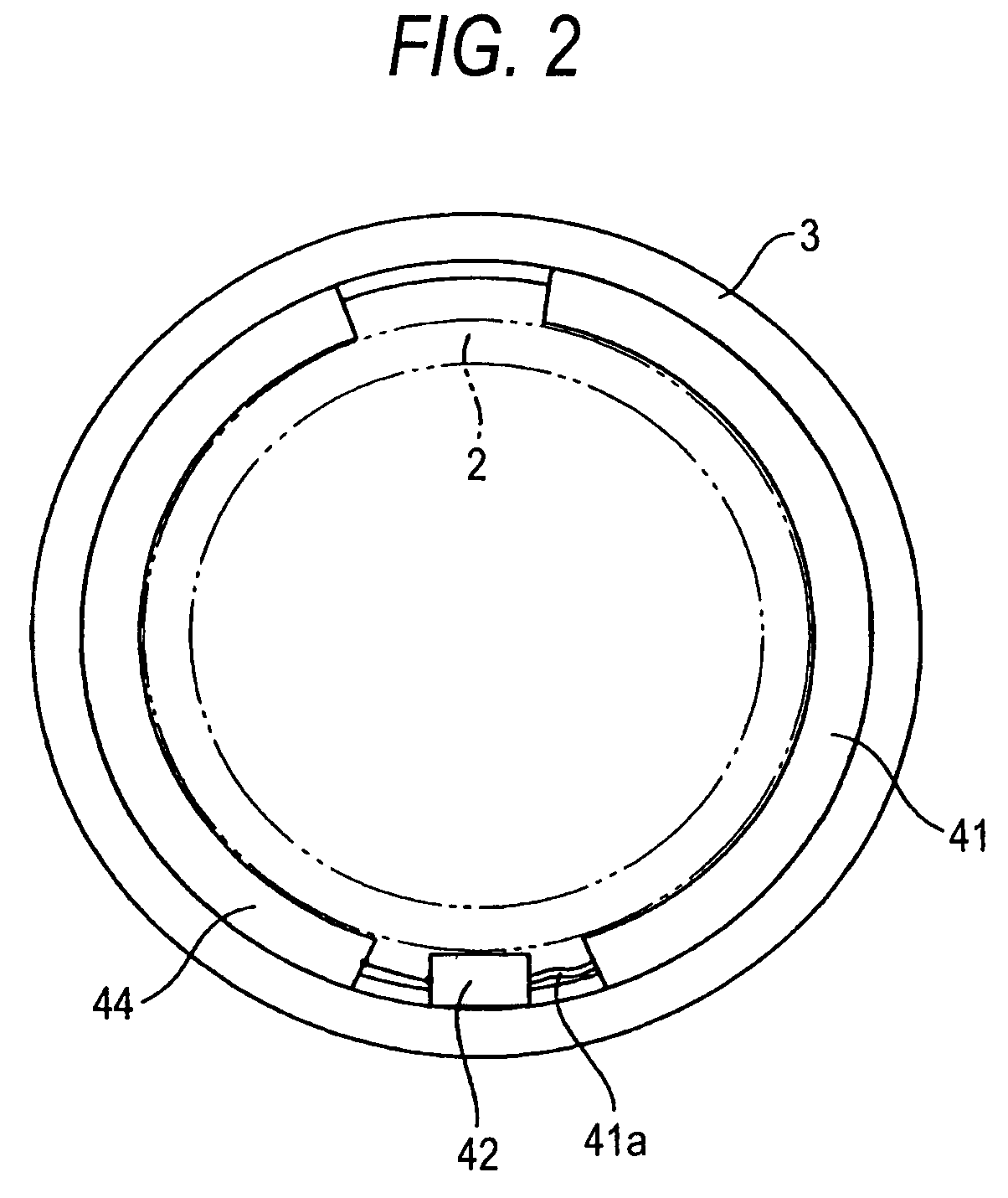
[0035]FIG. 1 is an axially parallel sectional view of an embodiment in which the invention is applied to an angular ball bearing, and FIG. 2 is a front view of an outer ring spacer 3 of the angular ball bearing which results as viewed from the left in FIG. 1.

[0036]This embodiment shows an example in which an oil supply unit 4 is disposed on, of an inner ring spacer 2 and the outer ring spacer 3 which are disposed adjacent to each other in an angular ball bearing 1, the outer ring space 3 which constitutes a spacer on a stationary side of the bearing 1. The angular ball bearing 1 has a construction in which a plurality of rolling elements (balls) 13 are held at predetermined intervals in a circumferential direction between an inner ring 11 and an outer ring 12 while being accommodated individually in a plurality of pockets 14a formed in a cage 14, and in this embodiment, the outer ring 12 i...


PUM

PropertyMeasurementUnit
circumferenceaaaaaaaaaa
speedaaaaaaaaaa
noise levelaaaaaaaaaa

Abstract

A groove is formed on one end face side of a cage including a plurality of pockets for holding individually rolling elements which extends circumferentially along a full circumference of the cage about a rotational center thereof and has a bottom portion which communicates individually with the plurality of pockets, and a distal end portion of a nozzle of an oil supply unit is inserted into the groove, whereby the generation of disturbance to airflow and negative pressure in the vicinity of an opening of the nozzle is suppressed when a rolling bearing rotates, so that lubricating oil supplied from the nozzle is allowed to reach the rolling elements in an ensured fashion.

Description

TECHNICAL FIELD[0001]The present invention relates to a rolling bearing device including a self-lubricating function.BACKGROUND ART[0002]Rolling bearings such as angular ball bearings are used for support of shafts which rotate at relatively high speed such as various types of spindles used on working tools. As lubricating methods for lubricating rolling bearings for supporting such spindles which rotate at high speed, conventionally, an oil-air lubricating method has mainly been used in many cases.[0003]The oil-air lubricating method is a method for blowing a minute amount of lubricating oil which is intermittently supplied towards the rolling bearing through piping by virtue of compressed air, and in this method, since the lubricating oil is supplied to the bearing by being caused to forcibly pass through an air curtain formed around the rolling bearing which rotates at highs speed, the compressed air is used as a so-called carrier.[0004]In the oil-air lubricating method like this...

Claims


Application Information

Patent Timeline
Patent Type & Authority Patents(United States)
IPC IPC(8): F16C19/00F16C33/38
CPCF16C19/163F16C33/3856F16C33/414F16C33/6659F16C33/6681F16C2322/39F16C2240/02F16C33/664F16C33/66F16C33/38F16N7/32F16N7/38
Inventor UENO, HIROSHISUZUKI, KAZUYAURANO, HIROYUKI
Owner JTEKT CORP
Why Eureka
Try Eureka