Water drainage from soils is a very critical problem that relates to many important applications that affect our everyday life.
Lack of proper drainage of undesirable water from soil exacts a tremendous cost from our economy while extracting
usable water from water wells is so essential for living in many areas around the nation and the world.
Here, in the United States, poor drainage, especially in the winter when freezing and thawing frequently occur, leads to deterioration and failure of pavements, the cost of which is measured in the billions of dollars annually.
Lack of soil drainage under homes and buildings causes heavy damage to the foundations and seepage of water and
moisture to subsurface building space.
This water or
moisture damages furniture as well as the structure and creates fungi like
mildew, extremely harmful to our health.
Lack of drainage behind retaining walls is a major cause of wall failures.
Lack of good interior drainage in sloped ground is a major cause of landslides when the ground becomes saturated after heavy
precipitation.
Drilling and developing water wells for the purpose of extracting water from the ground for domestic use or other uses (purposes) is quite expensive and
time consuming.
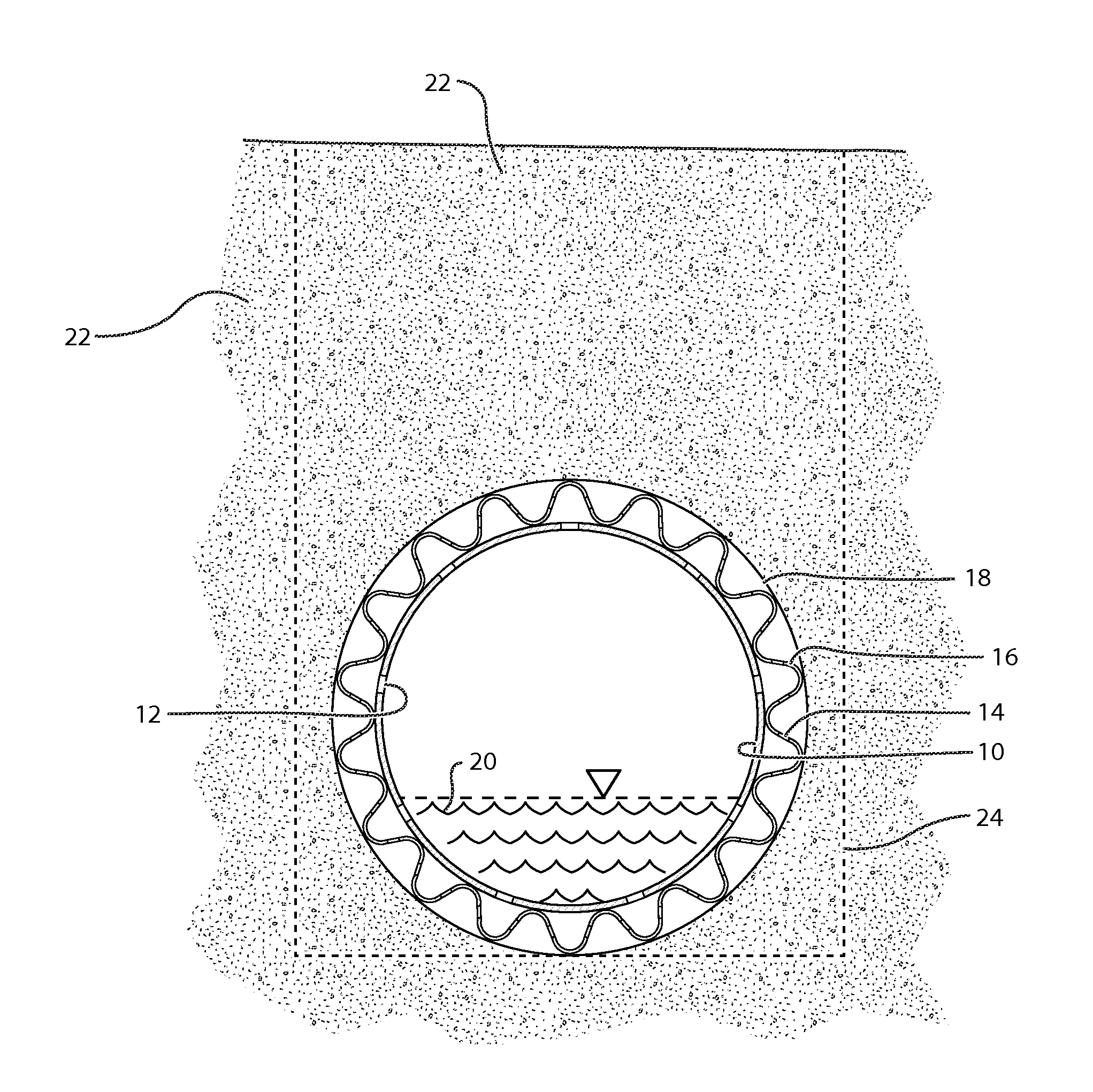
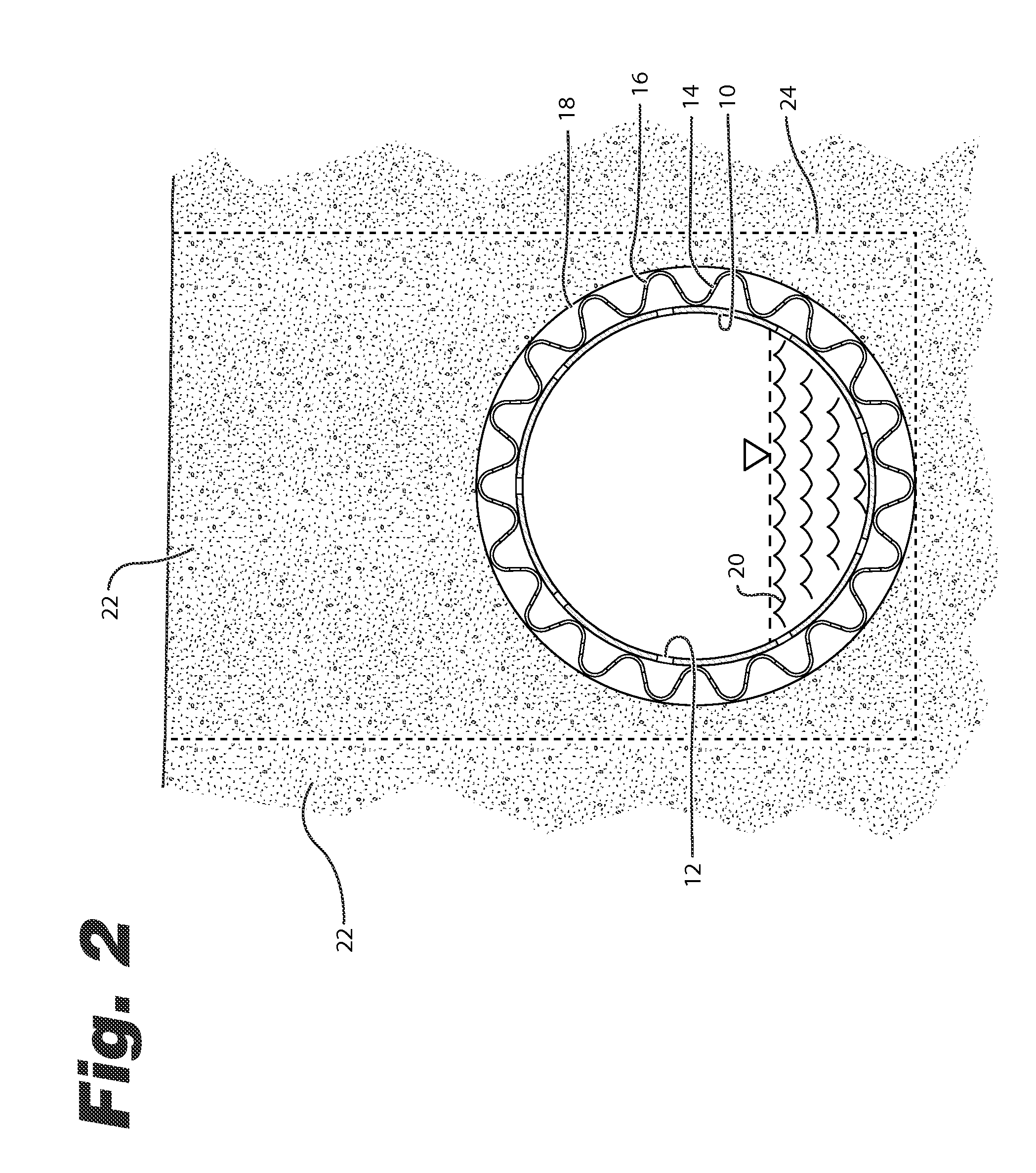
The disadvantages of this
system are that the corrugations impede
water flow due to induced turbulence, collected precipitates, and provide ideal
rodent nesting and
infestation environment.
This drain is also difficult to flush clean because the obstructions anchor themselves in the corrugations.
Once put in place into dug trenches, the drain requires back filling with
granular material to be effective, an added cost.
Without granular backfill, drainage is very limited to the small areas radial to the perforations.
Also, due to its thin construction, it suffers from low
compressive strength and collapse of the pipe from vehicular load is quite common.(ii) The so-called “French drain”, consists of a trench whose walls are lined (or unlined) with a filter fabric and backfilled with sand and / or gravel.
It requires a relatively large trench, which means large trench excavation and large amounts of granular backfill material at high cost.
This drain suffers from low flow velocity which prevents the removal of water in a timely manner.
When lined with a filter fabric, the installation of this drain becomes more labor intensive.
The added material and labor increases the cost significantly.(iii) The geocomposite edge drain, or strip drain, which consists of a cuspate or dimpled plastic skeleton core of a nominal width, usually 24 inches maximum and wrapped all around with geotextile filter fabric.
This drain suffers from low core capacity and the hindrance of longitudinal flow (velocity) by the manner in which the core is constructed.
As a result, loss of fine soil and cavitations under the floor slabs can arise with the passage of time and produce loss of support.
Failure to do so may increase the design
pressure load by a factor of 2 or more.
In the second case, the safety of the
drainage flow is more assured, however at higher material and labor costs.
This means a much higher cost for material and labor and a shortened design life.
Ground slopes, like the side of a hill, are many times prone to very damaging landslides such as what happens in California, the Northwest United States and elsewhere.
This is especially true during periods of heavy
precipitation when the ground gets saturated and the build up of
pore water pressure in the soil increases the driving forces and reduces the resisting forces, thus resulting in landslides that can destroy buildings and expensive homes that are built on these hills, and can cause blocking of roads and highways that are built on the sides of the hills, even rendering them impassable.
At present, most of these situations go without corrective treatments and spectacular failures take place.
The current state of the art technology for horizontal drains employ steel or PVC pipes with evenly spaced slots or perforations and may be fitted with a knitted tubular geotextile sleeve or a simple wrapping of geotextile sheet, though this is not recommended in most situations because the sleeve can inhibit the effectiveness of cleaning and thus promote clogging.
The major downfall of these pipes is that they do not effectively drain large amounts of water quickly enough.
As can be implied, the process of installing the well intake screen and filter is difficult,
time consuming, expensive, and may not give the most desirable results.
This drain suffers from limited drainage and major
erosion and loss of valuable soil due to
piping that occurs through the joints.
This is complicated and expensive to use a good graduated granular filter in the trench around the pipe.
This problem has been neglected so far, thus losing to
contamination very valuable land.

