Circuit breaker and opening and closing method thereof

a circuit breaker and opening and closing technology, applied in the field of circuit breaker, can solve the problems of less maneuverability of the vacuum valve operating mechanism, and achieve the effects of reducing rebound, high maneuverability, and easy cancellation of closed sta

Inactive Publication Date: 2011-03-22
HITACHI LTD
View PDF19 Cites 13 Cited by
  • Summary
  • Abstract
  • Description
  • Claims
  • Application Information

AI Technical Summary

Benefits of technology

[0009]The present invention has been made in view of the above circumstances and an object thereof is to provide a circuit breaker which enables an electromagnetic repulsion driving mechanism to easily cancel the closed state and reduces the rebound of a movable electrode shaft in the course of current interruption in a simple manner and provides high maneuverability, and an opening and closing method thereof.

Problems solved by technology

However, the above conventional circuit breakers are compelled to provide a large electromagnetic repulsion driving mechanism and a larger power supply capacity because they not only have to obtain a prescribed opening speed but also require an electromagnetic repulsive force exceeding the attractive force of a permanent magnet for holding the closed state.
In addition, the vacuum valve operating mechanism can become less maneuverable due to its size.

Method used


Image

  • Circuit breaker and opening and closing method thereof
  • Circuit breaker and opening and closing method thereof
  • Circuit breaker and opening and closing method thereof

Examples


first embodiment

[0030]First, the method of use and the method of operation for an embodiment of a commutation type DC circuit breaker as a circuit breaker according to the present invention will be described referring to FIGS. 5 to 7.

[0031]In FIG. 5, reference numeral 1 represents a DC power supply which supplies 1500 V through its positive pole in an ordinary DC feeding circuit. Reference numeral 2 represents a load such as a train. Reference numeral 3 represents a feeding line which supplies electricity to the load and reference numeral 4 represents a flyback line which connects the load 2 and the DC power supply 1. The commutation type DC circuit breaker 5 as a circuit breaker according to the present invention is inserted midway in the feeding line 3 and switches electric power supplied from the DC power supply 1 to the load 2.

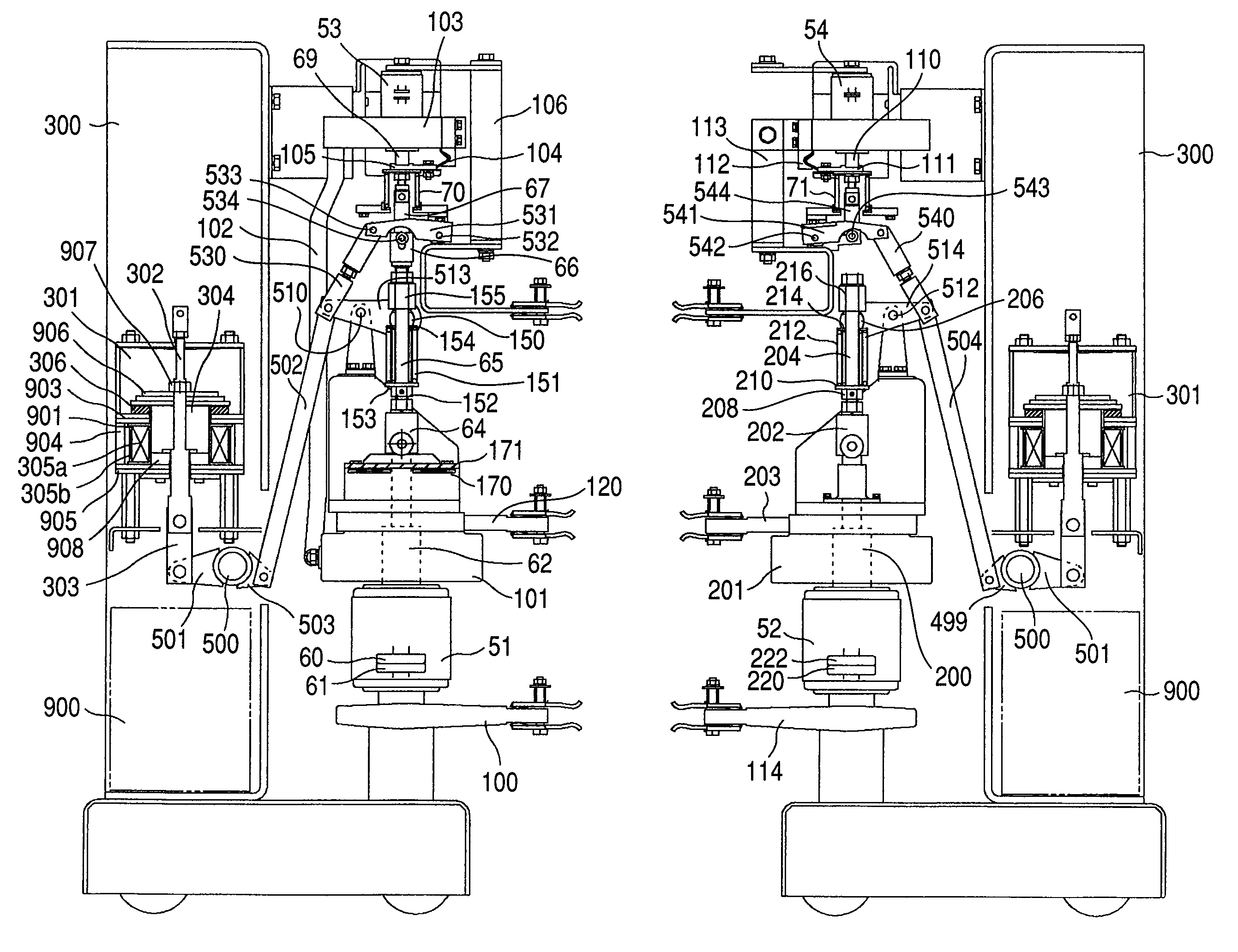
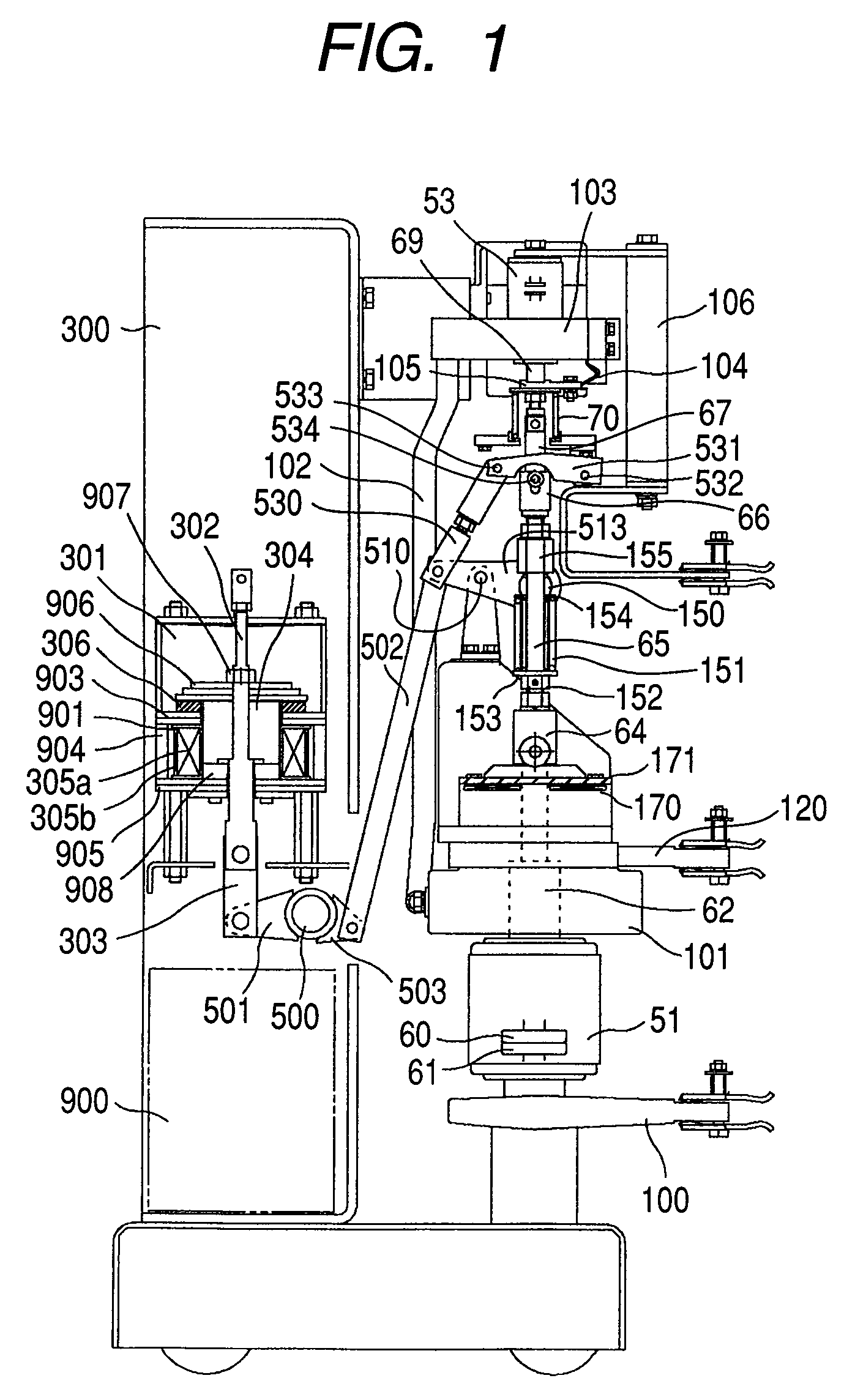
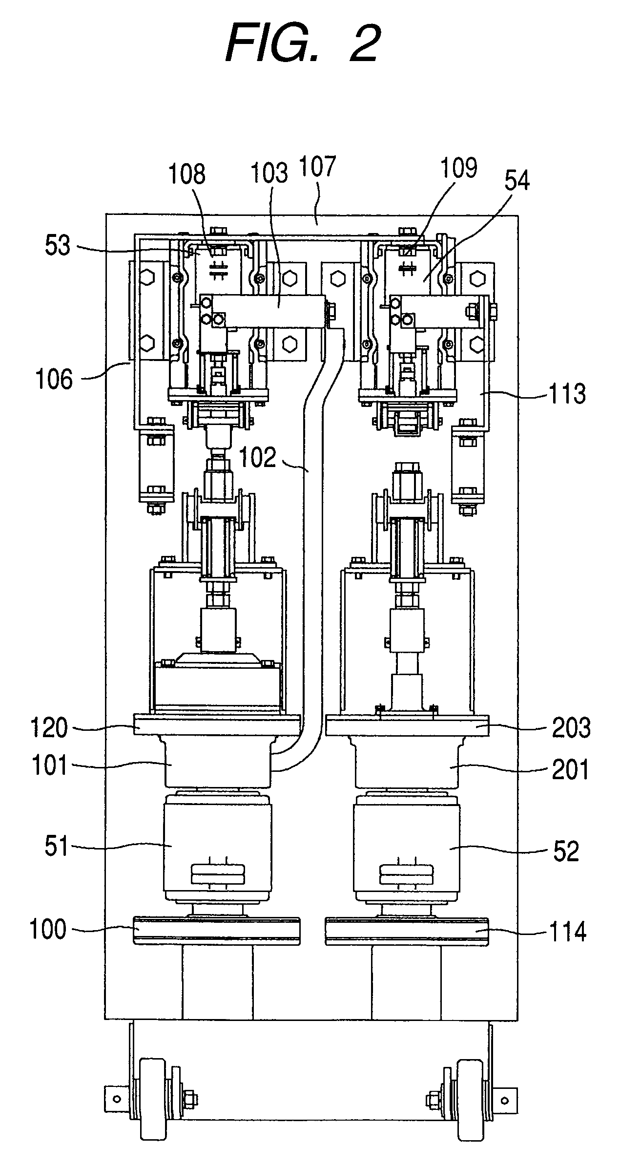
[0032]The commutation type DC circuit breaker 5 is comprised of four switches, a first main switch 51, a second main switch 52, a first sub switch 53 and a second sub swi...

second embodiment

[0073]FIGS. 11 to 13 show an embodiment of a three-phase high speed circuit breaker 600 as a circuit breaker according to the present invention, in which FIG. 11 is a right side sectional view of the three-phase high speed circuit breaker 600 as a circuit breaker according to the present invention, FIG. 12 is a back view thereof, and FIG. 13 is a front view thereof, all indicating the closed state. In these figures, the parts designated by the same reference numerals as in FIGS. 1 to 4 are the same parts.

[0074]In these figures, the three-phase high speed circuit breaker 600 includes a vacuum valve 601 incorporating a freely releasable contact. A fixed conductor 602 of a fixed electrode of the vacuum valve 601 is connected with a fixed feeder 603 located on the upper side. On the other hand, a movable conductor 604 of its movable electrode is electrically conductive to a movable feeder 606 through a power collector 605.

[0075]The movable conductor 604 is coupled with one end of an ins...


PUM

PropertyMeasurementUnit
time lag t1aaaaaaaaaa
currentaaaaaaaaaa
circuit resistanceaaaaaaaaaa

Abstract

A circuit breaker includes a vacuum valve, an electromagnet including a first coil for driving an operating shaft of the vacuum valve toward an opening direction by electromagnetic repulsion, a movable core and a permanent magnet. Further, an operating mechanism is provided which excites the first coil to close the vacuum valve, holds the vacuum valve closed by an attractive force of the permanent magnet and excites the first coil in a direction reverse to an excitation direction in closing operation to open the vacuum valve. In the circuit breaker, together with the first coil, a second coil is disposed which is excited simultaneously with an electromagnetic repulsion coil for a quick opening operation by electromagnetic repulsion is provided in the electromagnet.

Description

CLAIM OF PRIORITY[0001]The present application claims priority from Japanese application serial No. 2006-353644, filed on Dec. 28, 2006, the content of which is hereby incorporated by reference into this application.FIELD OF THE INVENTION[0002]The present invention relates to a circuit breaker and more particularly to a circuit breaker provided with an opening means which quickly drives an operating shaft of a vacuum valve toward an opening direction by electromagnetic repulsion, and an opening and closing method thereof.BACKGROUND OF THE INVENTION[0003]An opening means which quickly drives an operating shaft of a vacuum valve toward an opening direction by electromagnetic repulsion comprises an electromagnetic repulsion coil and a ring copper plate located opposite to it where the vacuum valve is opened by quickly exciting the electromagnetic repulsion coil of the opening means by a capacitor discharge or the like and using an electromagnetic repulsive force such as eddy current wh...

Claims


Application Information

Patent Timeline
Patent Type & Authority Patents(United States)
IPC IPC(8): H01H9/00H01H33/66H01H3/00H01H51/00H01H77/06H01H75/00H01H33/02H01F7/08
CPCH01H33/6662H01H33/596H01H33/38H01H33/6641H02B13/0354
Inventor MORITA, AYUMUHOSODA, MINORUMATSUDA, YOSHIHIKOSUZUKI, MASATOMIYASHITA, KEIICHIOOUCHI, SHIGETOSHISAITOU, MASAAKIYANO, AKIHITO
Owner HITACHI LTD
Why Eureka
Try Eureka