Vehicle airbag device

a technology for airbags and occupants, applied in the direction of vehicular safety arrangments, pedestrian/occupant safety arrangements, vehicle components, etc., can solve the problem of inability to close the vent hole, and achieve the effect of ensuring the protection performance of the occupant's head and efficient protection of the occupan

Inactive Publication Date: 2011-04-12
TOYOTA JIDOSHA KK
View PDF12 Cites 19 Cited by
  • Summary
  • Abstract
  • Description
  • Claims
  • Application Information

AI Technical Summary

Benefits of technology

[0009]It is an object of the invention to provide a vehicle airbag device which opens and closes a vent hole by using a tether, and which is able to efficiently protect an occupant, particularly, an occupant's head, regardless of whether or not the occupant is wearing webbing, and which secures the occupant's head protection performance even in the case of an oblique collision, and which is less subject to external factors such as surrounding configurations and the like.
[0011]According to the first aspect of the invention, when a collision occurs, the gas generation portion is activated to generate gas. The generated gas is supplied into the airbag that is housed in the folded state. Therefore, the airbag is inflated and deployed to the occupant side, so that the airbag receives the occupant's upper body that includes the head and that is moving by inertia. When the occupant's upper body that includes the head contacts the inflated airbag, the internal pressure of the airbag heightens but gas is let out through the vent holes that are formed in the two side portions of the airbag, so that the internal pressure of the airbag is appropriately kept.
[0012]More concretely, in the case where an occupant is wearing the webbing, since the webbing restrains the inertia movement of the occupant's upper body that includes the head to a vehicle front side, the occupant's head moves forward and obliquely downward relative to the vehicle by inertia, so that the amount of advancement of the occupant's head into the airbag becomes small. Therefore, the pressing force that acts on the intermediate portion of the tether disposed in the airbag becomes less than a predetermined value (including the case where the intermediate portion of the tether is not pressed at all), so that an open state of the vent holes formed in the two side portions of the airbag is maintained by the vent hole opening-closing control portion. Hence, since gas is let out from inside the airbag through the vent holes, the internal pressure of the airbag is appropriately kept.
[0013]On the other hand, in the case of an occupant not wearing the webbing, since the webbing does not restrain the inertia movement of the occupant's upper body that includes the head to the vehicle forward side, the occupant's head moves to the vehicle forward side by inertia immediately upon a collision. Therefore, the amount of the occupant's head into the airbag becomes large, so that the pressing force (tension) that acts on the intermediate portion of the tether disposed in the airbag becomes greater than or equal to a predetermined value. Therefore, due to the vent hole opening-closing control portion, the pair of left and right side portions of the tether are moved relative to the internal side surfaces of the two side portions of the airbag so as to close the vent holes. Hence, the internal pressure of the airbag is maintained at a high level, so that the occupant's upper body that includes the head is appropriately restrained.

Problems solved by technology

However, according to the construction disclosed in the foregoing related technology, the vent hole additionally provided in a central portion of the upper surface of the airbag is closed by the windshield pane, and therefore there is a problem as follows.
Besides, since the foregoing airbag is constructed so that the vent hole formed at the center of the upper surface of the airbag is closed from outside the airbag by utilizing the windshield pane, there is a possibility that a gap may form between the vent hole and the windshield pane so that the vent hole cannot be closed, depending on the curved surface shape of the windshield pane, or the curved surface shape of the upper surface of the airbag at the time of inflation and deployment.

Method used


Image

  • Vehicle airbag device
  • Vehicle airbag device
  • Vehicle airbag device

Examples


first embodiment

[0025]A first embodiment of a vehicle airbag device in accordance with the invention will be described hereinafter with reference to FIGS. 1 to 4. Incidentally, arrows FR appropriately shown in these drawings show a vehicle forward side, and arrows UP show a vehicle upward side, and arrows IN show an inward side in the vehicle width direction.

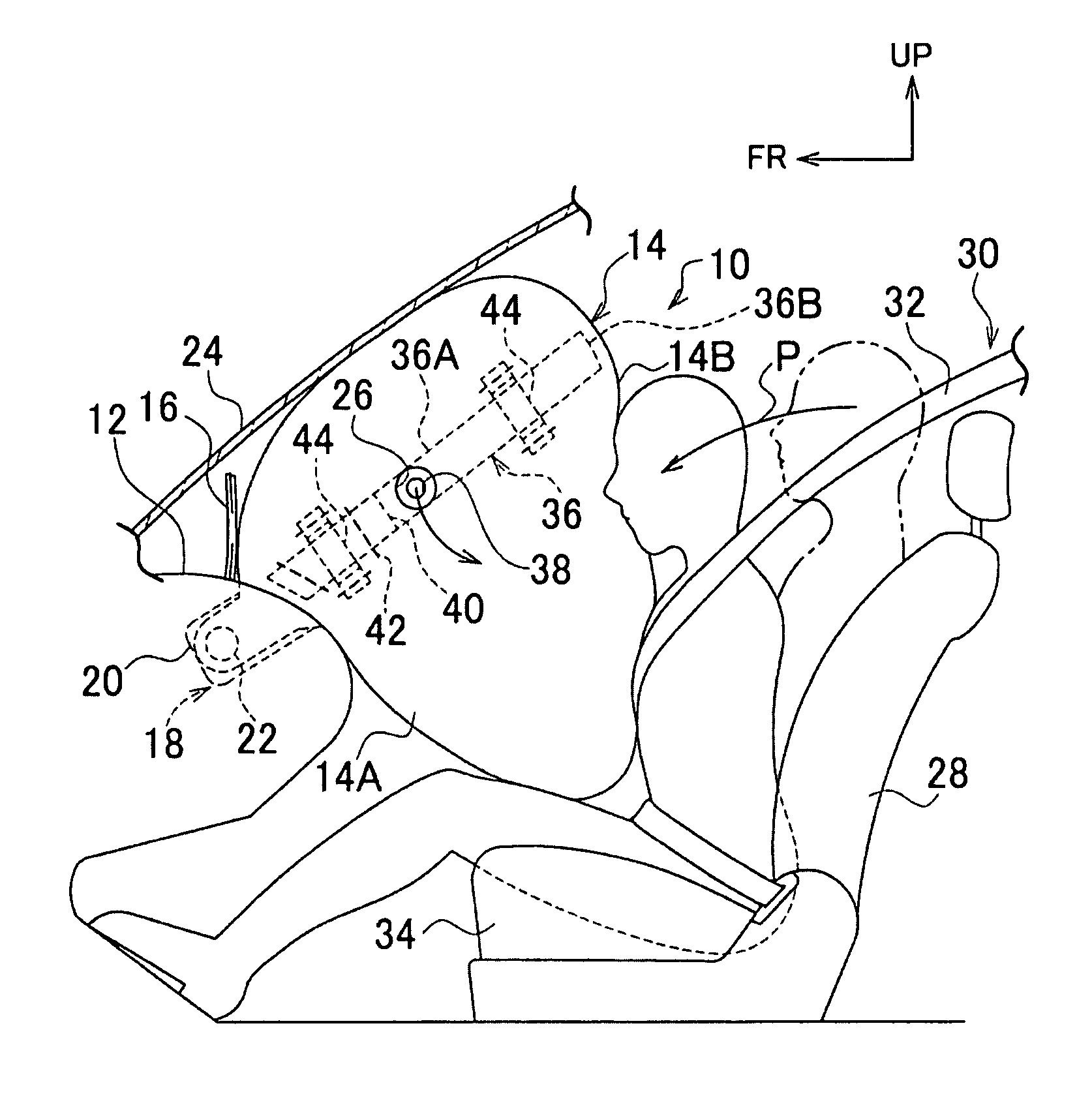
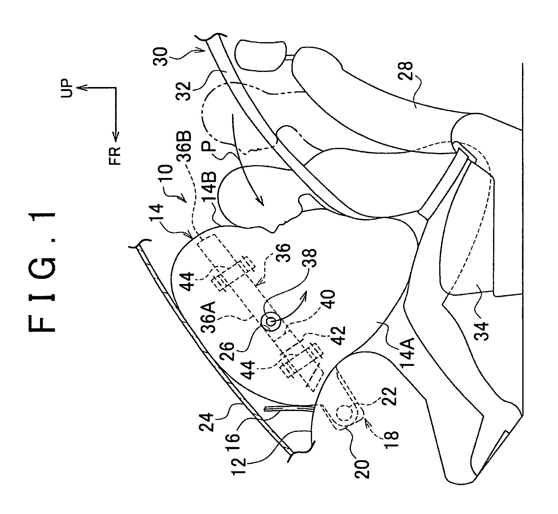
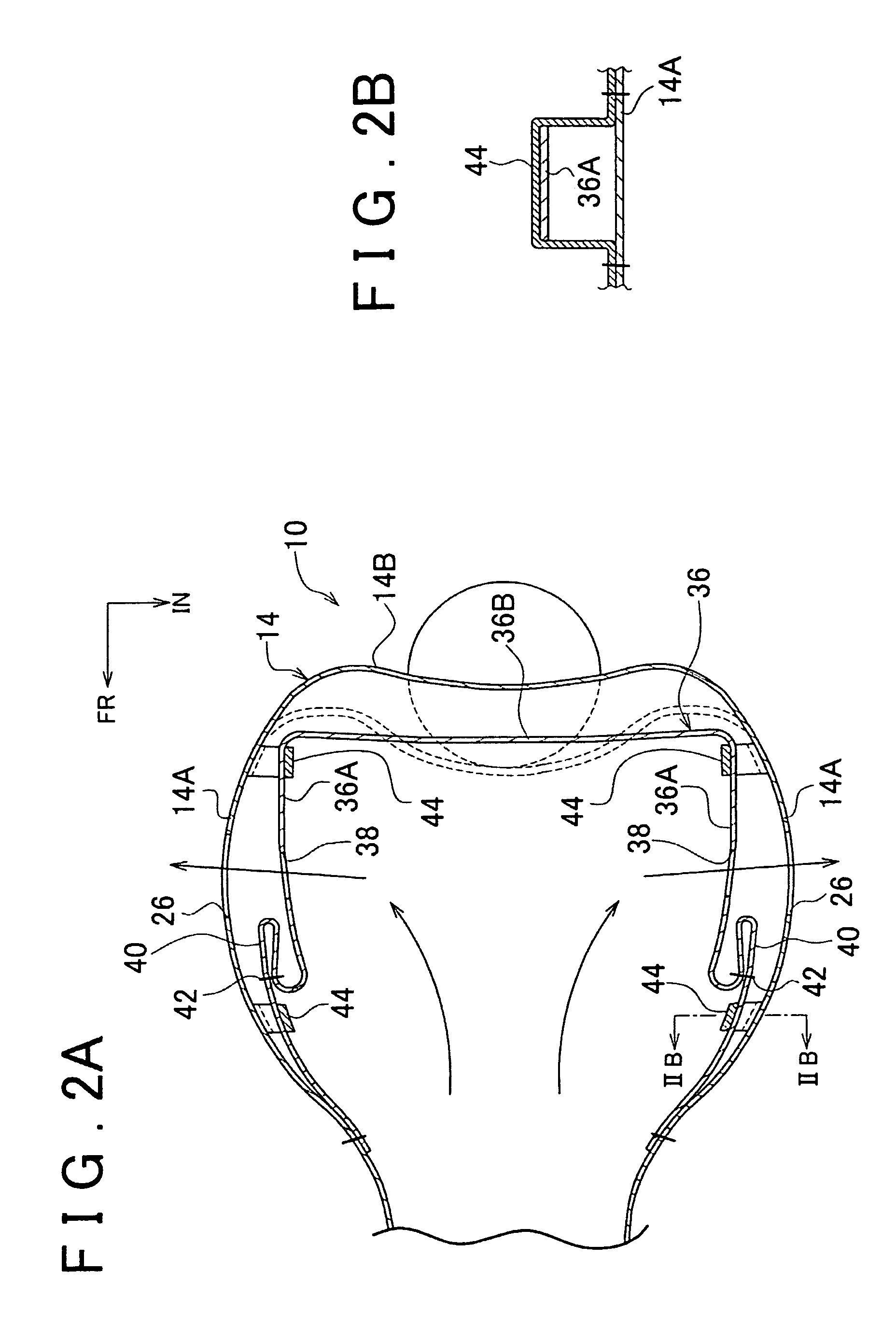
[0026]FIG. 1 shows a side view illustrating a state in which a passenger seat airbag device in accordance with the embodiment has activated, and has inflated and deployed a passenger seat airbag to an occupant that is wearing webbing. Besides, FIG. 2A shows a horizontal sectional view of the passenger seat airbag. Furthermore, FIG. 3 shows a side view illustrating a state in which the passenger seat airbag device in accordance with the embodiment has activated, and has inflated and deployed the passenger seat airbag to an occupant that is not wearing webbing. Besides, FIG. 4 shows a horizontal sectional view of the passenger seat airbag.

[0027]A...

second embodiment

[0049]Next, a second embodiment of the vehicle airbag device in accordance with the invention will be described with reference to FIGS. 5 to 7. Incidentally, the same component portions and the like as those of the first embodiment will be given the same reference characters, and descriptions thereof will be omitted below.

[0050]As shown in FIG. 5, in a passenger seat airbag device 50 in accordance with the second embodiment, a tether 54 formed in a squared U shape in a plan view is disposed within a passenger seat airbag 52. Concretely, the tether 54 is constructed of a pair of left and right side portions 54A extending along internal side surfaces of two side portions 52A of the passenger seat airbag 52, and an intermediate portion 54B connecting occupant-side end portions of these two side portions 54A.

[0051]Base end portions of the pair of left and right side portions 54A are fixed by sewing near end portions of the two side portions 52A of the passenger seat airbag 52 that are o...


PUM


Abstract

A vehicle airbag device includes: an airbag which is housed in a folded state when a gas generation portion is not activated, and which inflates and deploys by receiving gas when the gas generation portion is activated, and whose two side portions are provided with gas outlet vent holes; and a tether that includes pair of left and right side portions extending along internal side surfaces of the two side portions of the airbag, and an intermediate portion interconnecting occupant-side end portions of the pair of left and right side portions. The airbag devices closes the vent holes by moving the pair of left and right side portions relative to the internal side surfaces of the two side portions of the airbag when the pressing force on the intermediate portion of the tether is greater than or equal to a predetermined value.

Description

INCORPORATION BY REFERENCE[0001]The disclosure of Japanese Patent Application No. 2008-041834 filed on Feb. 22, 2008 including the specification, drawings and abstract is incorporated herein by reference in its entirety.BACKGROUND OF THE INVENTION[0002]1. Field of the Invention[0003]The invention relates to a vehicle airbag device in which an airbag is provided with a vent hole.[0004]2. Description of the Related Art[0005]Japanese Patent Application Publication No. 2002-2439 (JP-A-2002-2439) discloses a structure that mechanically controls the opening and closing of vent holes formed in an airbag corresponding to whether or not an occupant is wearing webbing. This related technology will be briefly described. That is, in an airbag device for a passenger seat, vent holes are formed at three locations in the airbag, concretely, the left and right side surfaces and an upper surface of the airbag. Incidentally, the upper surface of the airbag substantially faces the windshield pane.[000...

Claims


Application Information

Patent Timeline
Patent Type & Authority Patents(United States)
IPC IPC(8): B60R21/239B60R21/205B60R21/2338B60R21/276
CPCB60R21/233B60R21/2338B60R2021/23382B60R2021/23316
Inventor FUKAWATASE, OSAMUYAMADA, SHUJISANADA, AKIYOSHI
Owner TOYOTA JIDOSHA KK
Why Eureka
Try Eureka