
Fastening assembly and cushion having fastening assembly

a technology of fastening assembly and fastening structure, which is applied in the direction of socks, other domestic articles, synthetic resin layered products, etc., can solve the problems of defective products, waste of production costs, and the inability of the hook-and-loop fastener to fasten with the corresponding fastening structure, etc., and achieves the effect of easy removal and convenient secure position

Active Publication Date: 2011-04-19
TAIWAN PAIHO LTD
View PDF51 Cites 12 Cited by
  • Summary
  • Abstract
  • Description
  • Claims
  • Application Information

AI Technical Summary

Benefits of technology

"The present invention provides a fastening assembly for use in a foaming process. The assembly includes a first strip with hooks on its surface and a second strip with a protective layer covering the hooks. The protective layer prevents damage to the hooks from the foam material. The assembly also includes a magnetic substance, making it easy to secure the assembly in position during the foaming process and remove it afterwards. The invention also provides a cushion with the fastening assembly integrated into it, allowing for easy attachment and protection of the hooks during the foaming process."

Problems solved by technology

However, during the foaming process, the foam material tends to cover the hooks of the hook-and-loop fastener so that, after the foam material is set, the hooks of the hook-and-loop fastener cannot fasten with corresponding fastening structures.
Thus, a defective product is produced, and the production cost is wasted.
If the hook-and-loop fastener is not securely positioned at the predetermined location in the mold, the pushing force generated during the foaming process will push the hook-and-loop fastener away from the predetermined location so that the molded product is defective, with the hook-and-loop fastener displaced.
However, this temporary protective film has to be removed after the molding process by heating or by use of chemicals, which involves a complicated removing procedure and is very inconvenient.

Method used


Image

  • Fastening assembly and cushion having fastening assembly
  • Fastening assembly and cushion having fastening assembly
  • Fastening assembly and cushion having fastening assembly

Examples


Embodiment Construction

[0025]Disclosed herein are a fastening assembly and a cushion having the same. Since the physical principles involved in the present invention and the basic connection relationships among related elements are well known to persons of ordinary skill in the art, a detailed description of such principles and relations is omitted herein. Besides, the drawings referred to in the following description are not and need not be drawn according to actual dimensions for they are intended to demonstrate features of the present invention only schematically.

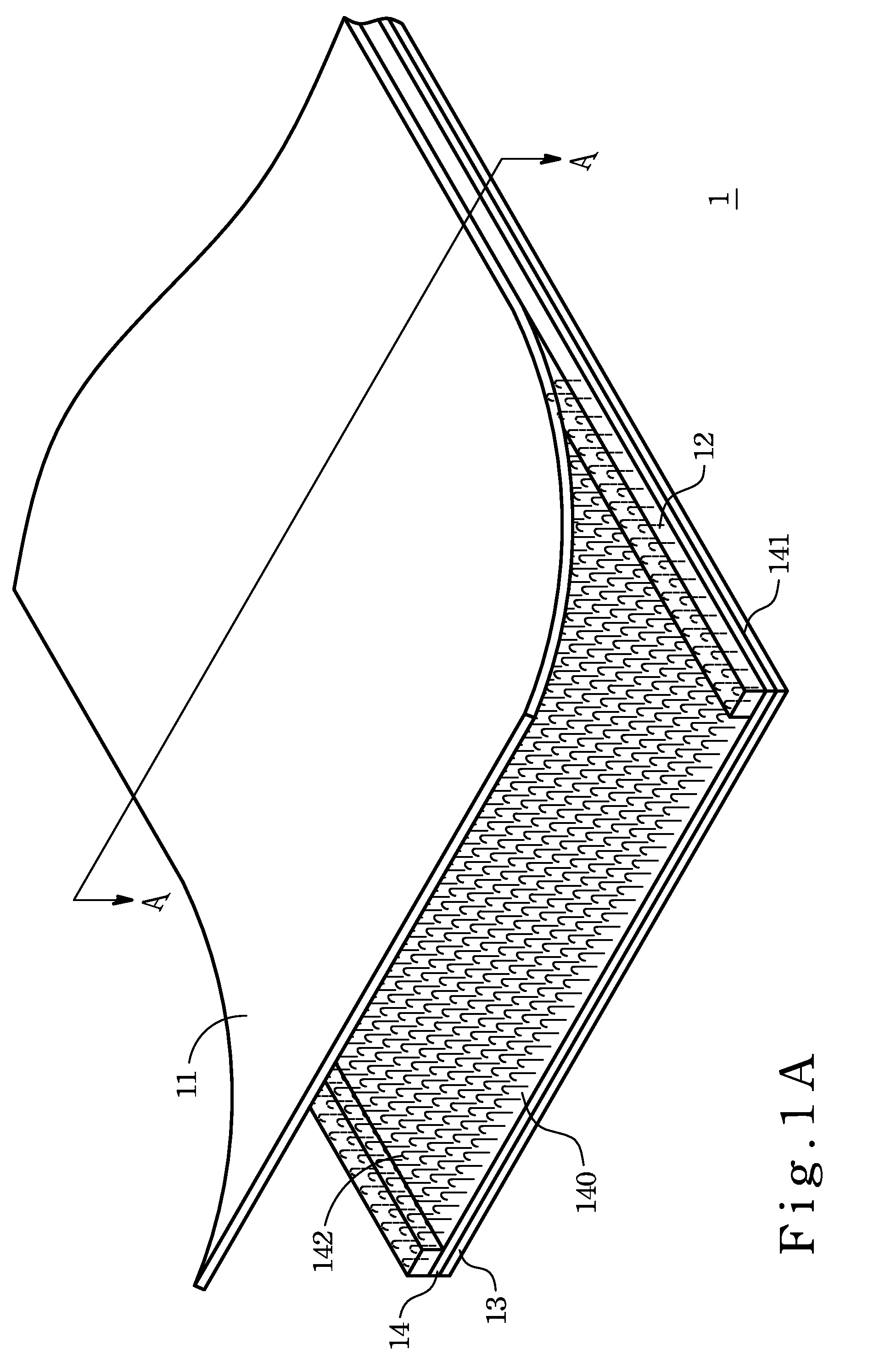
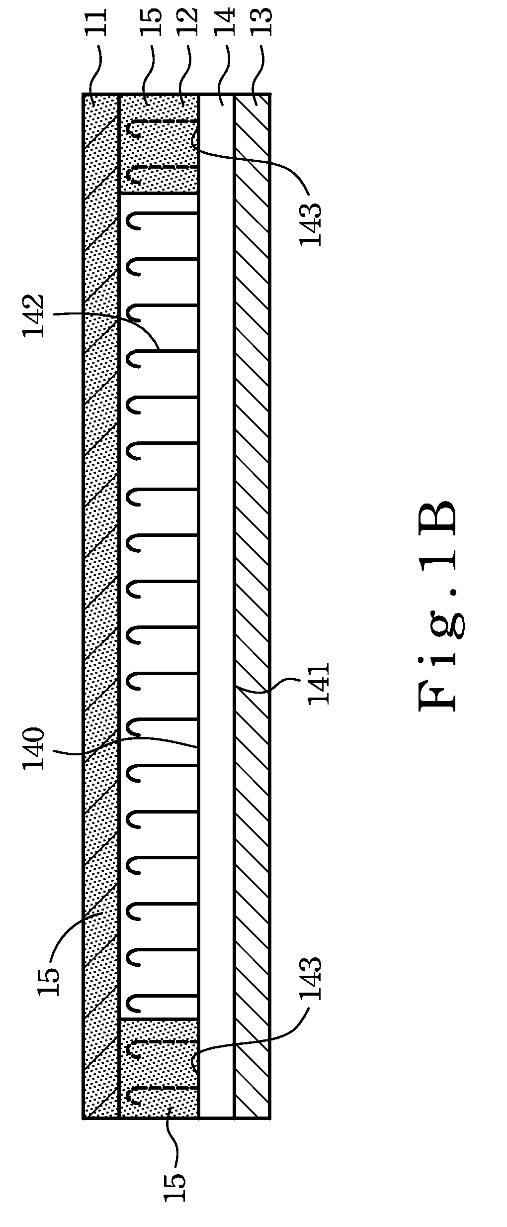
[0026]Please refer to FIG. 1A and FIG. 1B. FIG. 1A is a perspective view of a fastening assembly 1 according to a first preferred embodiment of the present invention and FIG. 1B is a sectional view of the fastening assembly 1 taken along a line AA in FIG. 1A. The fastening assembly 1 comprises a first strip 14, a second strip 13, a first protective layer 12, and a second protective layer 11. The first strip 14 has a first surface 140 protrudin...


PUM

PropertyMeasurementUnit
magneticaaaaaaaaaa
ferromagneticaaaaaaaaaa
shapeaaaaaaaaaa

Abstract

A fastening assembly and a cushion having the same are provided. The fastening assembly includes a first strip and a second strip. The first strip has a first surface protrudingly provided with a plurality of hooks, and a second surface to which the second strip is bonded. The fastening assembly further includes a first protective layer and a second protective layer, both comprising a magnetic substance. The first protective layer is disposed lengthwise along both lateral sides of the first surface of the first strip so as to form sidewalls respectively and embed some of the hooks. The second protective layer is attached to the first protective layer so as to cover the hooks on the first surface of the first strip.

Description

BACKGROUND OF THE INVENTION[0001]1. Technical Field[0002]The present invention relates to a fastening assembly and, more particularly, to a fastening assembly co-molded with a foam article.[0003]2. Description of Related Art[0004]The conventional hook-and-loop fastener, or better known by the brand name Velcro, was invented by George de Mestral, a Swiss engineer, under the inspiration of burrs. The hook-and-loop fastener comprises a hook side where tiny hooks are disposed thereon and a loop side covered with even smaller and finer loop-like fastening structures. When the hook side and the loop side are pressed together, the hooks on the hook side engage with the loop-like fastening structures on the loop side so that the two sides are fastened together.[0005]In recent years, the hook-and-loop fastener, which is easily assembled and detached, is often coupled and used with other articles. When a hook-and-loop fastener is applied to a foam article such as a seat cushion, a buffer pad,...

Claims


Application Information

Patent Timeline
Patent Type & Authority Patents(United States)
IPC IPC(8): A44B18/00
CPCA47C31/023B32B7/08B32B27/20B32B29/02B32B27/40Y10T428/24174Y10S428/90Y10T428/24017B32B5/022B32B5/18B32B27/065B32B27/10B32B3/02B32B3/08B32B2264/105B32B2307/208B32B2601/00A47C27/00A47C27/22A47C27/12
Inventor CHENG, SEN-MEI
Owner TAIWAN PAIHO LTD
Learn More