Optical pickup and optical data processing device using the same

a technology of optical pickup and optical data processing device, which is applied in the field of optical pickup, can solve the problems of difficult detection of track error signals in the case of bd optical recording media by the dpp system, the output of suitably amplified track error signals, and the difficulty of suitably detecting the track error signals of optical recording media having different track pitches with one optical pickup using the dpp system

Inactive Publication Date: 2011-04-19
RICOH KK
View PDF33 Cites 0 Cited by
  • Summary
  • Abstract
  • Description
  • Claims
  • Application Information

AI Technical Summary

Benefits of technology

[0002]The present invention relates to an optical pickup including an optical element and more particularly to an optical pickup capable of obtaining suitable track error signals during reading and / or writing for multiple optical recording media having different track pitches, and an optical data processing device using the optical pickup.

Problems solved by technology

Therefore, the offset component contained in the push-pull signal Sa is completely removed or significantly reduced, which leads to output of a suitably amplified track error signal.
However, the DPP system involves the following practical disadvantages.
In this structure, the positional intervals between the three focus light spots which are adjusted to detect the optimal track error signals for an HD optical recording medium are not suitable for a BD optical recording medium, meaning that the track error signals are difficult to detect in the case of the BD optical recording medium by the DPP system.
That is, suitably detecting the track error signals of optical recording media having different track pitches with one optical pickup using the DPP system is difficult, depending on the combination of optical recording media.
However, in this method, an unused sub-spot is formed on the optical recording medium so that the track error signals are not suitably detected.
However, arranging such a grating is not easy due to layout limitations.

Method used


Image

  • Optical pickup and optical data processing device using the same
  • Optical pickup and optical data processing device using the same
  • Optical pickup and optical data processing device using the same

Examples


embodiment 1

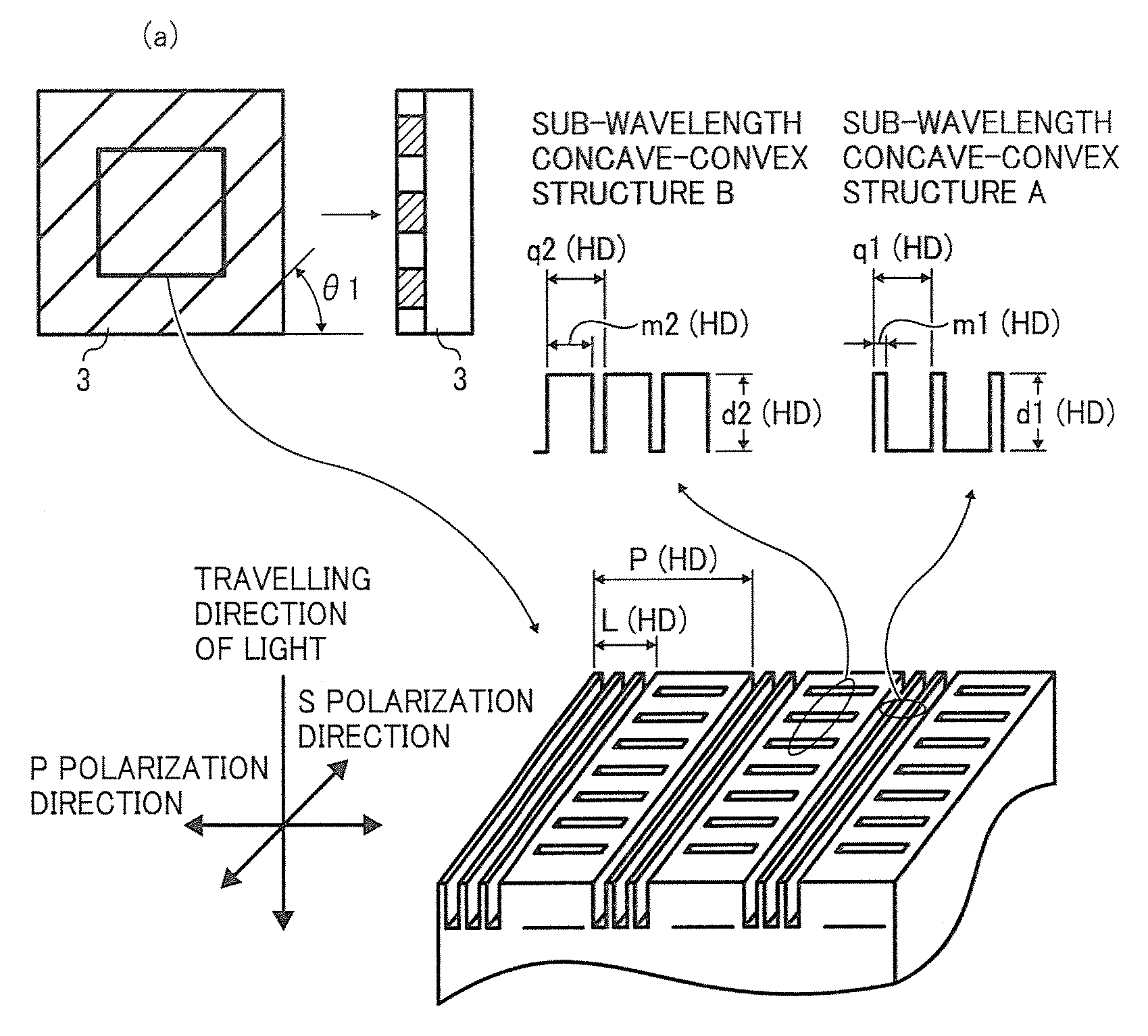
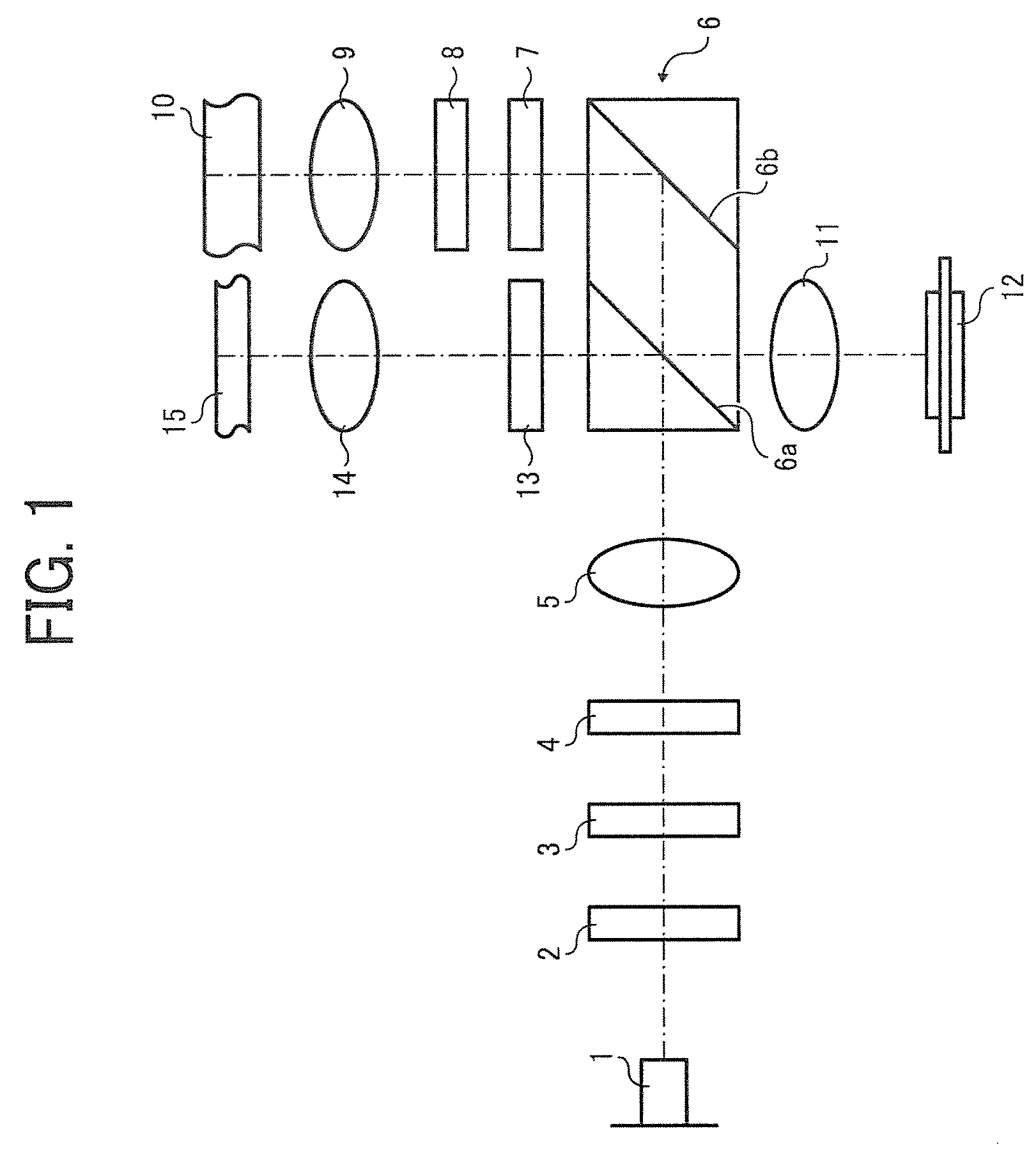
[0055]FIG. 1 is a schematic diagram illustrating an embodiment of the structure of the optical pick up having a liquid crystal element and two diffraction elements of a polarization selection type of the present invention. In FIG. 1, a numeral reference 1 represents a semiconductor laser as a light source; a numeral reference 2 represents a liquid crystal element as a polarization switching device; a numeral reference 3 represents an HD diffraction element for 3 beams for an HD-DVD (hereinafter referred to as HD) as a first diffraction element, a numeral reference 4 represents a BD diffraction element for 3 beams for a Blu-ray disc (hereinafter referred to as BD) as a second diffraction element; a numeral reference 5 represents a collimate lens; a numeral reference 6 represents a light path splitting device of a polarization selection type (i.e., a polarization selective light path splitting device); a numeral reference 6a represents a polarization beam splitter surface; a numeral r...

embodiment 2

[0103]FIG. 9 is a schematic diagram illustrating an optical pickup of Embodiment 2 having a liquid crystal and a diffraction element of an area separation type and a polarization selection type. As illustrated in FIG. 9, the difference between the optical pickup described in Embodiment 1 and the optical pickup of Embodiment 2 is that the HD diffraction element 3 and the BD diffraction element 4 for 3 beams are replaced with a diffraction element 16 for 3 beams. As in the case of Embodiment 1, in this structure, the collimate lens 5, the ½ wavelength board 7, the ¼ wavelength boards 8 and 13 and the detection lens 11 are optional. The following is described about the structure having all the optional devices and elements.

[0104]In addition, (a) and (b) in FIG. 10 are diagrams illustrating the macro structure of the diffraction element 16. (a) is a diagram of the diffraction element 16 viewed from the light source side and (b) represents a cross section thereof. The diffraction element...

embodiment 3

[0111]FIG. 13 is a schematic diagram of Embodiment 3 illustrating an optical pickup which employs a light source rotation system and two diffraction elements of polarization selection type. As illustrated in FIG. 13, the optical pickup of Embodiment 3 is the same as the optical pickup of Embodiment 1 described above in FIG. 1 except that no crystal element is provided.

[0112]Another difference between Embodiments 1 and 3 is that the polarization direction of the light source illustrated in FIG. 14A is rotated 45° from S polarization direction. The polarization component at 45° direction can be decomposed into P polarization component and S polarization component. That is, the semiconductor laser 1 simultaneously emits a light beam of P polarization component and S polarization component.

[0113]This structure dispenses with the liquid crystal element 2 which functions as the electric device for use in Embodiment 1 and resultantly the number of man-hour for assembling an pickup is reduc...


PUM

PropertyMeasurementUnit
angleaaaaaaaaaa
angleaaaaaaaaaa
color wavelengthaaaaaaaaaa

Abstract

An optical pickup including a light source, two light focus devices, a light reception device, a polarization selective light path splitting device, a polarization switching device, a first diffraction element including a periodic structure including two kinds of sub-wavelength convexo-concave structures while the two kinds of sub-wavelength convexo-concave structures alternately arranged at right angles to each other, and the filling factors of the two kinds of sub-wavelength convexo-concave structures are determined to substantially equalize effective refractive indices of the two kinds of sub-wavelength convexo-concave structures with regard to the polarization direction of the outgoing light beam, and the second diffraction element having a structure similar to that of the first diffraction element except that the filling factors are determined to substantially equalize effective refractive indices of the two kinds of sub-wavelength convexo-concave structures with regard to a polarization direction perpendicular to the polarization direction of the outgoing light beam.

Description

BACKGROUND OF THE INVENTION[0001]1. Field of the Invention[0002]The present invention relates to an optical pickup including an optical element and more particularly to an optical pickup capable of obtaining suitable track error signals during reading and / or writing for multiple optical recording media having different track pitches, and an optical data processing device using the optical pickup.[0003]2. Discussion of the Background[0004]An optical pickup typically has a structure which detects focus error signals and track error signals and controls the position of an objective lens by using these error signals to correctly irradiate a predetermined recording track in an optical recording medium. With regard to the detection of track error signals, a 3-spot system, a push-pull system, and a differential push-pull system (hereinafter referred to as the DPP system or simply DPP) are typical well known examples.[0005]In particular, the DPP system uses a relatively simple optical syste...

Claims


Application Information

Patent Timeline
Patent Type & Authority Patents(United States)
IPC IPC(8): G11B7/135
CPCG11B7/0903G11B7/1367G11B7/1369G11B7/1353G11B7/094G11B2007/0006
Inventor HIRAI, HIDEAKI
Owner RICOH KK
Why Eureka
Try Eureka