Expandable eyewear with snap-together bridge

a technology of eyewear and snap-together bridge, which is applied in the direction of spectales/goggles, protective garments, goggles, etc., to achieve the effect of easy putting on or taking off eyewear

Inactive Publication Date: 2011-04-26
CLIC GOGGLES
View PDF8 Cites 29 Cited by
  • Summary
  • Abstract
  • Description
  • Claims
  • Application Information

AI Technical Summary

Benefits of technology

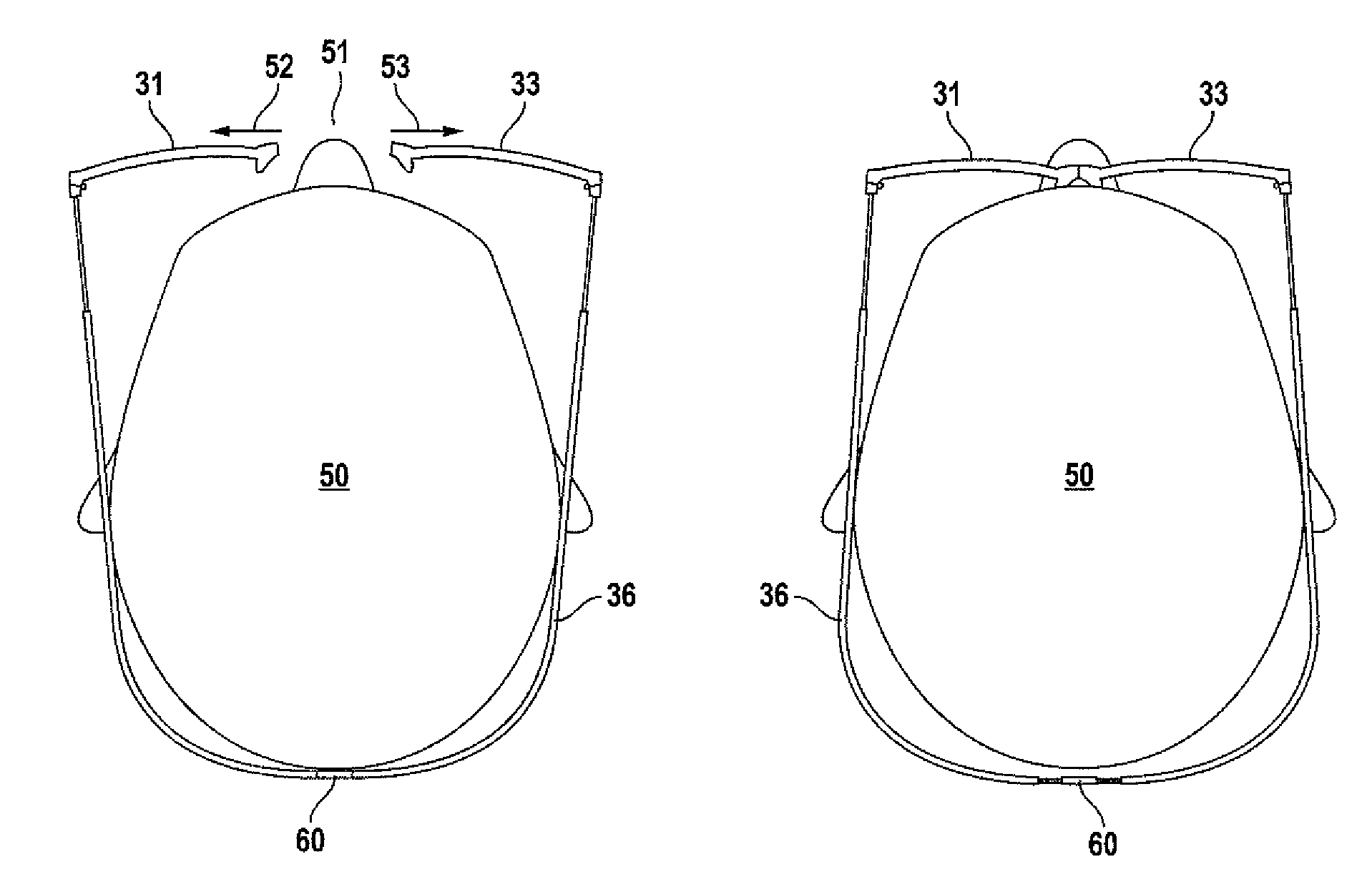
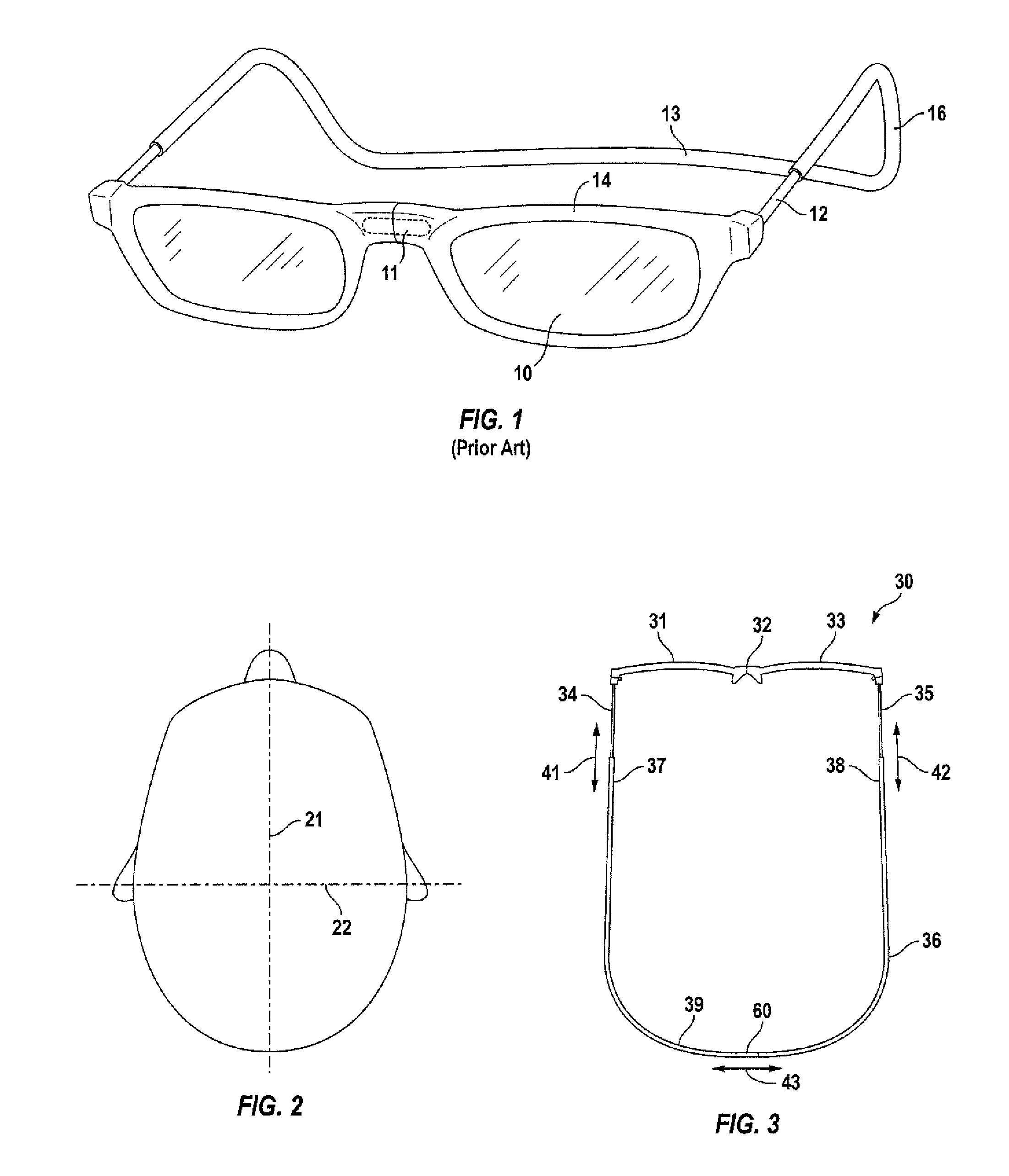
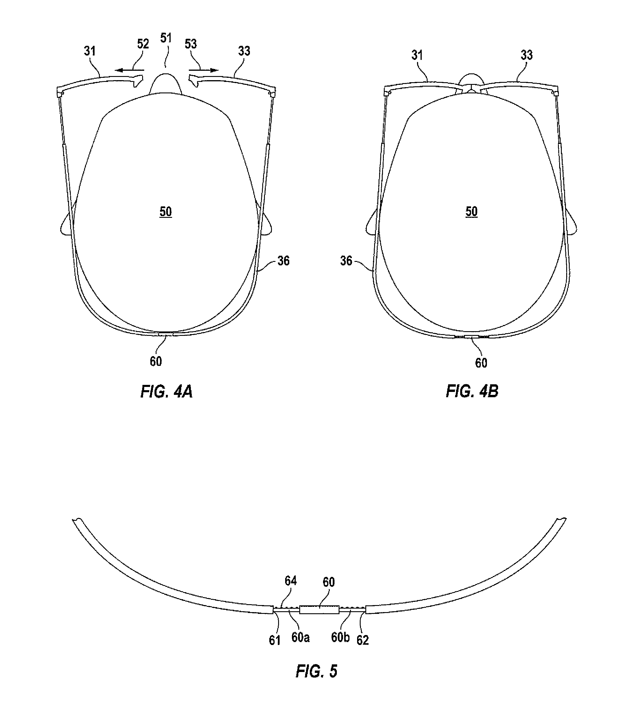
[0007]The present eyewear includes a pair of lenses, a pair of releaseable connectors connected to respective inner ends of the lenses, a pair of temples pivotally connected to respective outer ends of the lenses and a rigid strap connected between rear ends of the temples. The strap is generally U-shaped having substantially parallel legs connected to an arc-shaped base, the substantially parallel legs being connected to rear ends of the temples and when worn, the arc-shaped base extends along the back of a user's head. The strap at its U-shaped base is provided with a telescoping segment for selectively altering the length of the arc-shaped base for altering the spacing between the strap's substantially parallel legs to adjust the strap for varying widths of a user's head. The inner ends of the lenses are releasably secured together by connectors. In use, the lenses are separated from each other and pivoted outwardly, the strap wrapped around the back of a user's head and adjusted for size. The lenses are then pivoted towards each other and secured together in front of the user's eyes. The lenses are instantly separable for easily putting on or taking off the eyewear, but they are instantly connectable together for a secure and accurate fit.

Problems solved by technology

However, the former eyewear disclosed by applicant had no way to accommodate users whose heads were particularly wide thus having a dimension along axis 22 which is of considerable proportion.

Method used


Image

  • Expandable eyewear with snap-together bridge
  • Expandable eyewear with snap-together bridge
  • Expandable eyewear with snap-together bridge

Examples


Embodiment Construction

[0013]Novel features which are characteristic of the invention, as to organization and method of operation, together with the further objects and advantages thereof will be better understood from the following description considered in conjunction with the accompanying drawings, in which preferred embodiments in the invention are illustrated by way of example. It is to be expressly understood, however, that the drawings are for illustration description only and are not intended as definitions of the limits of the invention. The various features of novelty which characterize the invention are recited with particularity in the claims.

[0014]There has been broadly outlined the more important features of the invention in the summary above in order that the detailed description which follows may be better understood, and in order that the present contribution to the art may be appreciated. There are, of course, additional features of the invention that will be described hereinafter and wh...


PUM


Abstract

The present eyewear includes a pair of lenses, a pair of releaseable connectors connected to respective inner ends of the lenses, a pair of temples pivotally connected to respective outer ends of the lenses and a rigid strap connected between rear ends of the temples. The strap is generally U-shaped having substantially parallel legs connected to an arc-shaped base, the substantially parallel legs being connected to rear ends of the temples and when worn, the arc-shaped base extends along the back of a user's head. The strap at its U-shaped base is provided with a telescoping segment for selectively altering the length of the arc-shaped base for altering the spacing between the strap's substantially parallel legs to adjust the strap for varying widths of a user's head. The inner ends of the lenses are releasably secured together by connectors. In use, the lenses are separated from each other and pivoted outwardly, the strap wrapped around the back of a user's head and adjusted for size The lenses are then pivoted towards each other and secured together in front of the user's eyes. The lenses are instantly separable for easily putting on or taking off the eyewear, but they are instantly connectable together for a secure and accurate fit.

Description

TECHNICAL FIELD[0001]The present invention deals with improved eyewear having a snap-together bridge feature.BACKGROUND OF THE INVENTION[0002]Applicant is the owner of U.S. Pat. No. 6,253,388. The invention disclosed and claimed in the '388 patent involved eyewear comprised of a pair of lenses, releaseable connectors connected to respective inner ends of the lenses, a pair of temples pivotable to respective outer ends of the lenses and a rigid strap attached between rear ends of the temples. The strap was taught to be positioned below the lenses so as not to interference with a hairdo or helmet. The inner ends of the lenses were taught to be releasably secured together by the connectors, preferably, magnets. To position the eyewear, the lenses are first separated from each other and pivoted outwardly. The strap is then wrapped around the back of a user's head and the lenses pivoted towards each other and secured together in front of the eyes. The lenses were taught to be instantly s...

Claims


Application Information

Patent Timeline
Patent Type & Authority Patents(United States)
IPC IPC(8): G02C3/00
CPCG02C5/20G02C5/02G02C2200/02
Inventor LANDO, RON
Owner CLIC GOGGLES
Why Eureka
Try Eureka