Computer method and apparatus for connection tree routing in visual modeling of software

a computer method and software technology, applied in the field of computer programming, can solve problems such as difficult to understand, reduce the accuracy of software,

Inactive Publication Date: 2011-04-26
INT BUSINESS MASCH CORP
View PDF7 Cites 4 Cited by
  • Summary
  • Abstract
  • Description
  • Claims
  • Application Information

AI Technical Summary

Problems solved by technology

1. Ensuring that connections keep synchronized in response to user movements in one or more of the participating connections. Moving one of the connections in the tree can destroy the integrity of the tree. Implementations to address this often over complicate the use cases for reorient and deletion of connections participating in the tree by managing the tree through the central “trunk” element. The “trunk” element is overloaded with responsibility in that it has to listen to all the participating connections, and manage attachment locations and changing connection
2. Support for multiple tree connection structures is not automatic—i.e. each tree has to be manually moved and manipulated out of the way of the other tree. The central “trunk” element described above would need knowledge of other participating “trunks” and adjust itself accordingly. The issue is then which tree trunk element is designated as prime in order to adjust overlap between trunks.
3. The connections have to be in the direction of the view they are targeting (“trunk”) versus the actual view the connection is logically connecting to. Special code has to be in place in order to understand that the real semantic target is the node that the trunk is connected to, not the “trunk”.
4. Persistence of this structure is not intuitive causing potential team scenario issues. What is the “trunk” persisted as in the model file, is it a node or a special case of a connection? This also causes issues with team based scenarios where 2 or more team members are modifying the same diagram file. If one team member changes the router to “oblique” style and another changes the router to “tree”, the resulting file difference between the 2 file changes would be considerable (new element+new target view) and is not easily understood by the merge integrator. The intuitive change would be a minor style change to route the connection differently.

Method used


Image

  • Computer method and apparatus for connection tree routing in visual modeling of software
  • Computer method and apparatus for connection tree routing in visual modeling of software
  • Computer method and apparatus for connection tree routing in visual modeling of software

Examples


Embodiment Construction

[0022]A description of preferred embodiments of the invention follows.

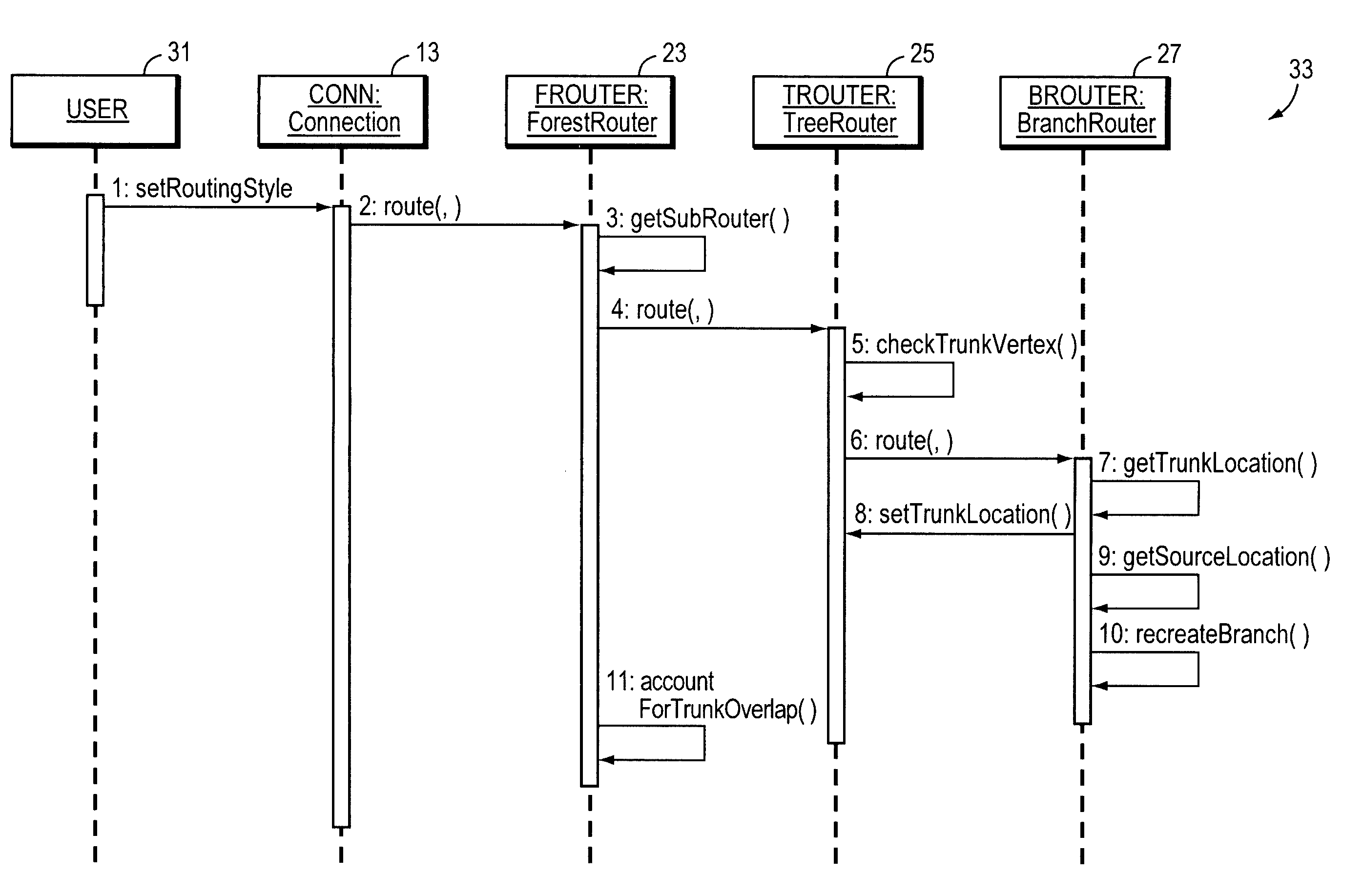
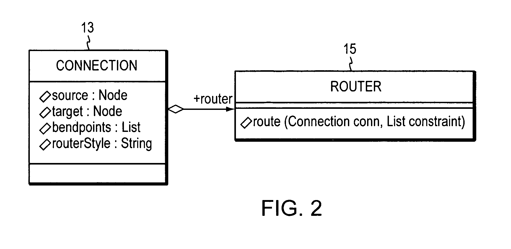
[0023]The present invention provides a solution to the problems of the prior art as follows. In the present invention, the tree routing style is considered to be a property of the connection itself, and a router object manages the location of the bendpoints to facilitate the tree look. A router is a class that understands how to modify the bendpoints of a connection based on a constraint. The constraint is often just another set of bendpoints that the user has defined through gestures on the modeling diagram. Using this router concept, the connection maintains its target as the end node instead of this interim “trunk” element. Then there is no need for custom handling of reorient and deletion since the behavior is the same as a connection merely routed with a different algorithm—i.e. “oblique routing”. Additionally, the file is afforded persistence since the connection is stored as a list of bendpoints with no nee...


PUM


Abstract

Computer method and apparatus for connection tree routing in visual modeling of software is disclosed. Tree routing style is represented as a property of a subject connection. A router object manages location of bendpoints of the subject connection in a connection tree. The subject connection maintains an end node as its target instead of a trunk element of the connection tree. The router object is formed of a hierarchy of routers including branch routers, tree routers and forest routers. Different routers maintain different aspects of the tree data forming display of the connection tree.

Description

BACKGROUND OF THE INVENTION[0001]In the art of computer programming, there are various tools to assist with the designing of a software program (e.g. application program). One category of such program design tools is the visual modeling type. The UML is an example visual modeling language (with formal syntax and semantics) for communicating a model or conceptionalization. The modeling language specification specifies modeling elements, notation and usage guidelines and not order of activities, specification of artifacts, repository interface, storage, run-time behavior and so forth.[0002]In general, at the modeling level a “problem” is posed in terms of a customer's needs and requirements and may be referred to as the business problem system. The software designer develops a “solution” software product and or service that addresses the problem. The UML syntax enables software designers to express (specify and document) the subject problems and solutions in a standardized manner, whi...

Claims


Application Information

Patent Timeline
Patent Type & Authority Patents(United States)
IPC IPC(8): G06F9/44
CPCG06F8/20
Inventor SHAW, STEVEN R.
Owner INT BUSINESS MASCH CORP
Why Eureka
Try Eureka