Packaging apparatus

a technology of packaging apparatus and packaging bag, which is applied in the field of packaging apparatus, can solve the problems of reducing the quality of package bags which will subsequently be manufactured, melting tape, etc., and achieves the effect of increasing production efficiency

Inactive Publication Date: 2011-05-03
ORIHIRO ENGINEERING CO LTD
View PDF29 Cites 3 Cited by
  • Summary
  • Abstract
  • Description
  • Claims
  • Application Information

AI Technical Summary

Benefits of technology

[0019]With the packaging apparatus according to the present invention, as described above, since the joint between the films is not placed in the horizontally sealed position, the horizontally sealed region is prevented from suffering a sealing failure, and the content is prevented from leaking out of the horizontally sealed region during the packaging operation. Consequently, the packaging apparatus can continuously manufacture package bags without any need to stop, and can have an increased production efficiency.

Problems solved by technology

If an attempt is made to thermally seal table B′, then the tape will be melted, causing problems.
Therefore, the problems (e.g., a portion of the melted tape is applied to a seal bar of the horizontal sealing mechanism which results in lowering the quality of package bags which will subsequently be manufactured) caused by the melted tape are prevented from arising.

Method used


Image

  • Packaging apparatus
  • Packaging apparatus
  • Packaging apparatus

Examples


Embodiment Construction

[0071]Exemplary embodiments of the present invention will be described below with reference to the drawings. FIG. 4 is a schematic view showing an arrangement of a packaging apparatus according to an exemplary embodiment of the present invention. FIG. 5A is a view showing a package bag manufactured by the packaging apparatus shown in FIG. 4.

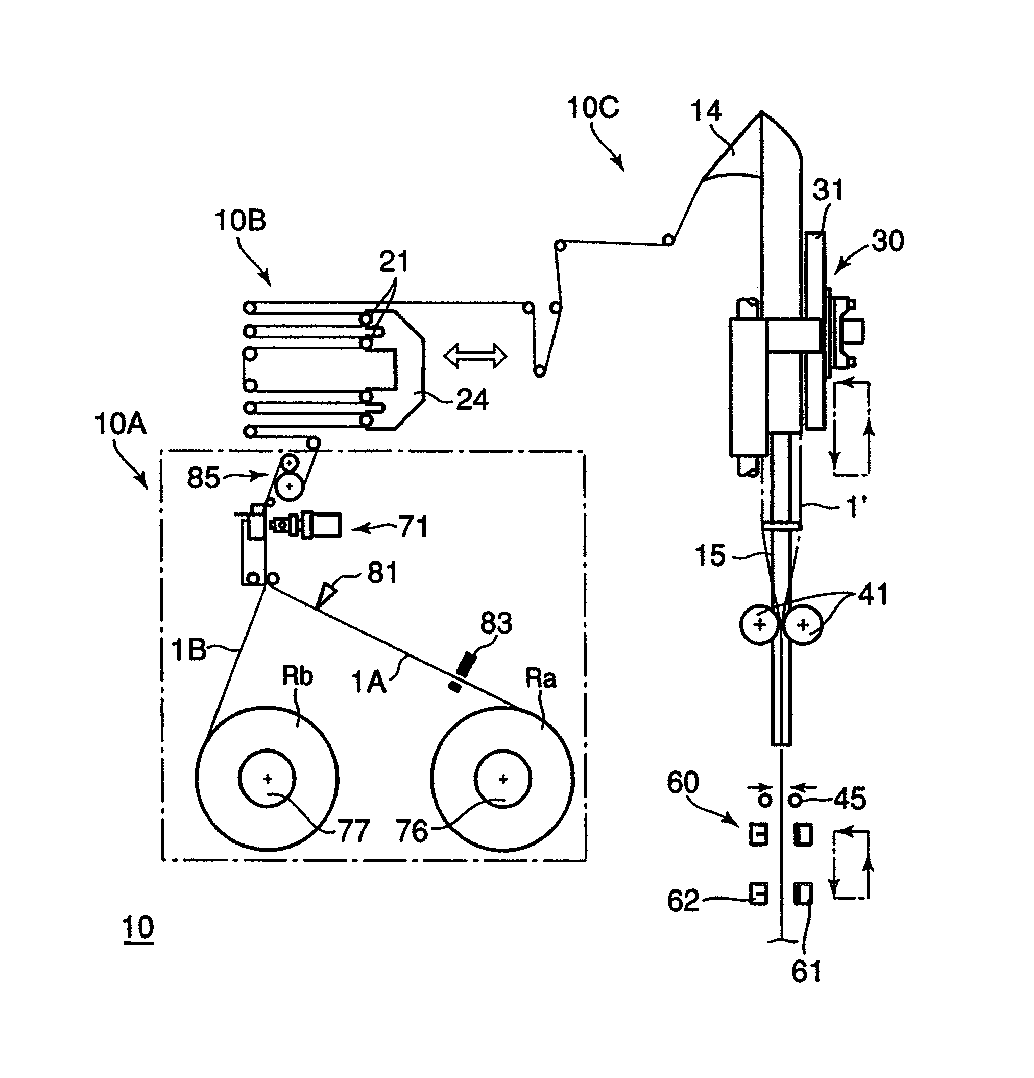
[0072]As shown in FIG. 4, packaging apparatus 10 according to the present exemplary embodiment generally comprises film supply mechanism 10A for reeling out films from film rollers Ra, Rb and joining film 1A and film 1B to each other when required, packaging mechanism 10C for forming vertically sealed regions and horizontally sealed regions in the films to continuously manufacture package bags, and film accumulator 10B positioned between film supply mechanism 10A and packaging mechanism 10C for guiding and holding the film in a meandering fashion.

[0073]As shown in FIG. 5A, package bag 91 manufactured by packaging apparatus 10 is a so-called pillo...


PUM

PropertyMeasurementUnit
lengthaaaaaaaaaa
lengthaaaaaaaaaa
period of timeaaaaaaaaaa

Abstract

There is provided a packaging apparatus including a mechanism for joining a film from a film roll and a film from another film roll to each other. The packaging apparatus is capable of preventing a joint of the films from suffering a thermal sealing failure thereby increasing production efficiency. Package apparatus (10) includes film supply mechanism (10A) for joining and supplying films (1A, 1B) and packaging mechanism (10C) for producing package bags from the film. Film accumulator (10B) for guiding and holding the film in a meandering fashion is disposed between film supply mechanism (10A) and packaging mechanism (10C). Some of accumulating rollers (21) of film accumulator (10B) are movable to a predetermined position depending on the size of package bags to be manufactured. The length of the film from a position in which the films are joined to each other to a position in which the film is horizontally sealed is changed to prevent the joint between the films from being placed in the position in which the film is horizontally sealed.

Description

TECHNICAL FIELD[0001]The present invention relates to a packaging apparatus for manufacturing a package bag filled with content such as a liquid, a viscous substance, or the like, from an elongate film reeled out from a film roll.BACKGROUND ART[0002]Heretofore, there has been known a filling packaging apparatus (hereinafter referred to simply as “packaging apparatus”) for continuously producing packaged products (package bags) filled with content such as a liquid, a viscous substance, or the like, for example. Generally, the packaging apparatus manufactures package bags by folding a film in the form of an elongate sheet reeled out from a film roll, into a tubular form, and feeding the content into the film and forming sealed regions on the film.[0003]FIG. 1 shows a film reeled out from a film roll. As shown in FIG. 1A, end marks A are normally applied in advance to a terminal end portion of the film that is wound on the film roll for indicating the end of the film. End marks A are r...

Claims


Application Information

Patent Timeline
Patent Type & Authority Patents(United States)
IPC IPC(8): B65B9/06B65B9/10B65B41/00B65B41/10B65B41/12B65B57/00
CPCB65B9/20B65B41/16B65B41/18B65H19/1852B65H23/1882B65B51/303B65B9/2007B65H2801/81B65H2301/512145B65H2701/1752B65B41/12
Inventor TSURUTA, ORIHIRONAGAI, KATSUMINAKAZATO, KAZUMI
Owner ORIHIRO ENGINEERING CO LTD
Why Eureka
Try Eureka