Switching power source

a power source and power factor technology, applied in the direction of electric variable regulation, process and machine control, instruments, etc., can solve the problems of increasing development cost, increasing current variation, excessive or insufficient current variation, etc., and achieve the effect of reducing noise, increasing power factor, and reducing nois

Inactive Publication Date: 2011-05-03
FUJI ELECTRIC CO LTD
View PDF12 Cites 13 Cited by
  • Summary
  • Abstract
  • Description
  • Claims
  • Application Information

AI Technical Summary

Benefits of technology

[0015]An object of the present invention is therefore to increase the power factor by reducing noise and loss, in particular, by reducing noise and loss by suppressing increase of the switching frequency. Another object of the invention is to simplify a power source system and thereby decrease its development cost by enabling easy switching between a critical-mode control method and a continuous-current-mode control method.
[0020]According to the invention, the switching element is on / off-controlled so that a current detection signal which corresponds to a current flowing through the inductor falls between two threshold value signals which are in phase with and similar, in waveform, to an input voltage and are proportional, in amplitude, to an error voltage signal. As a result, neither the on time nor the off time are fixed, and the switching element can be turned on and off automatically with optimum timing according to the input voltage state and the load state. The power factor can thus be increased. The switching frequency varies as the on time and the off time vary, and the spectrum of generated noise is spread. Noise reduction is thus enabled. Furthermore, when the threshold value signals come close to the reference potential, one reference value signal is set equal to the reference potential. As a result, the amplitude of the coil current does not decrease and hence increase of the switching frequency is suppressed. High-frequency noise can thus be reduced. Still further, switching to a critical-mode control method can be made easily by setting the control signal lower than the reference potential. This facilitates design change and hence enables reduction of the development cost.

Problems solved by technology

However, its application to uses with a heavy load is difficult because large current ripples occur and hence much stress is imposed on a coil and a diode.
This increases the development cost because, for example, the design of a power source system needs to be modified.
Therefore, if the off time is fixed as in the above conventional example, the current variation becomes excessive or insufficient.
This means a problem that the power factor cannot be increased beyond a certain limit.
The critical-mode control is difficult in the case where the off time is fixed as in the above conventional example.
The amplitude of the coil current becomes small and the switching frequency becomes very high, resulting in a problem that noise and switching loss are increased. FIG. 13A illustrates a relationship among the first and second threshold value signals Vth1 and Vth2 and the current detection signal Vi. FIG. 13B shows an on / off waveform of the switching element.
In this case, the switching frequency is high, resulting in a problem that noise and switching loss are increased. FIG. 14A shows a case that the difference between the first threshold value signal Vth1 and the second threshold value signal Vth2 is relatively large.

Method used


Image

  • Switching power source
  • Switching power source
  • Switching power source

Examples


Embodiment Construction

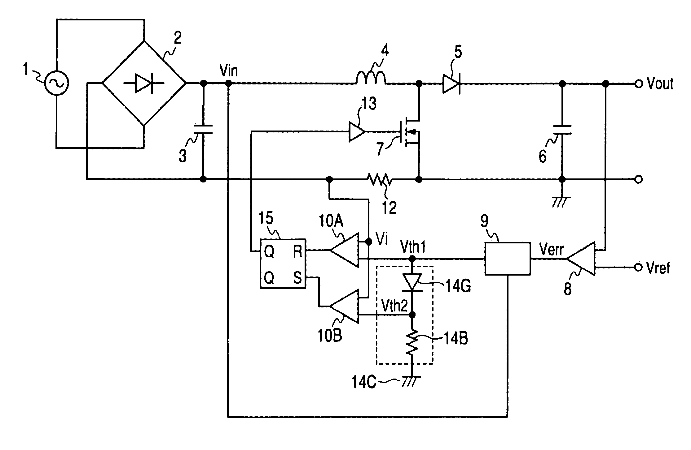
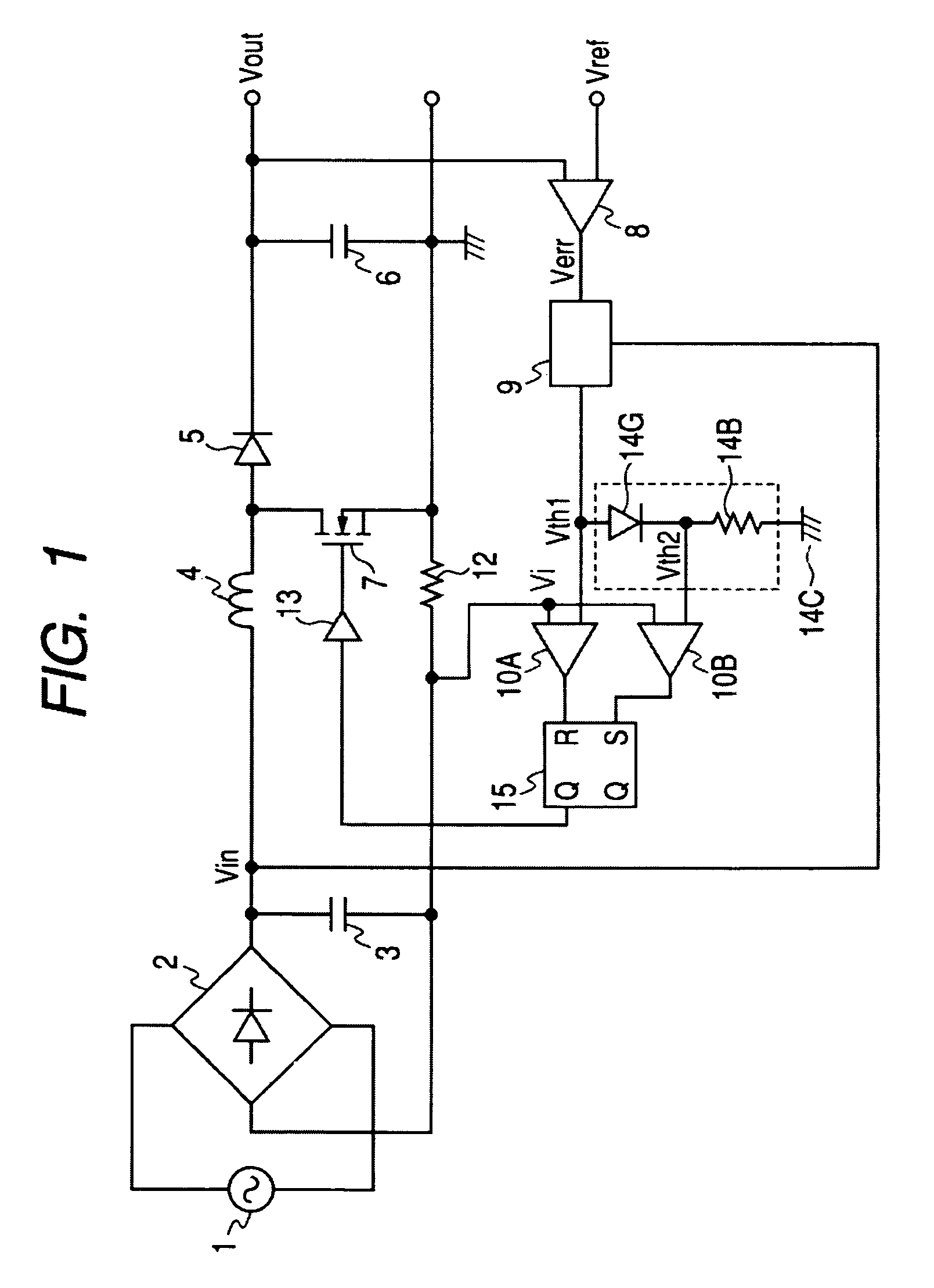
[0034]FIG. 1 is a circuit diagram of a switching power source according to an embodiment of the present invention. This is an improved version of the switching power source of FIG. 11, and the same components as shown in FIG. 11 will not be described in detail by giving them the same reference symbols as the corresponding components in FIG. 11. For example, in the switching power source of FIG. 1 a series circuit of a diode 14G and a resistor 14B is provided in such a manner that a first threshold value signal Vth1 (which corresponds to the threshold signal Vth in FIG. 11) and a reference potential 14C are applied to the diode 14G and the resistor 14B, respectively, that two comparators 10A and 10B are provided in place of the comparator 10 shown in FIG. 11, and a flip-flop 15 is provided in place of the monostable multivibrator 11 shown in FIG. 11. These different points will be described mainly below.

[0035]The voltage error amplifier 8 amplifies an error of the output voltage Vout...


PUM


Abstract

An error voltage Verr, as amplified by an amplifier, and an input voltage Vin, are multiplied together by a multiplier to generate a first threshold value signal Vth1, which is in phase with and similar in waveform to the input voltage Vin, and proportional in amplitude to the error voltage Verr. A second threshold value signal Vth2 is generated from the first threshold value signal Vth1 by a series circuit of a diode and a resistor. The power factor is increased by on / off-control of a switching element via a drive circuit, so that a current detection signal Vi, which is detected by a resistor and corresponds to an input current, falls between the two threshold value signals Vth1 and Vth2. Since the off time is not fixed, the noise spectrum is spread and increase of the switching frequency is suppressed. Noise reduction thus can be attained.

Description

BACKGROUND OF THE INVENTION[0001]1. Field of the Invention[0002]The present invention relates to a switching power source in which the power factor is increased by producing a stable DC power source from an AC power source and operating so that an input voltage and an input current of a chopper circuit are approximately in phase and have similar waveforms.[0003]2. Description of the Related Art[0004]Among the control methods for switching power sources of the above kind are a critical-mode control method in which control is made so that a switching element is turned on when a coil current becomes zero and a continuous-current-mode control method in which control is made so that a coil current does not become zero. In general, the critical-mode control method is advantageous for the purpose of noise reduction, as switching occurs when the coil current becomes zero, and hence switching noise is low. However, its application to uses with a heavy load is difficult because large current ...

Claims


Application Information

Patent Timeline
Patent Type & Authority Patents(United States)
IPC IPC(8): G05F1/656
CPCH02M1/4225Y02B70/126Y02B70/10
Inventor SHIMIZU, HIDEO
Owner FUJI ELECTRIC CO LTD
Why Eureka
Try Eureka