Light emitting sign and display surface therefor

a technology of light-emitting signs and display surfaces, which is applied in the direction of display means, instruments, spectral modifiers, etc., can solve the problems of increasing costs, poor color performance in daylight conditions, and a significant proportion of the total cost of signs, so as to reduce costs, improve light uniformity, and reduce costs

Inactive Publication Date: 2011-05-10
INTEMATIX
View PDF7 Cites 53 Cited by
  • Summary
  • Abstract
  • Description
  • Claims
  • Application Information

AI Technical Summary

Benefits of technology

[0012]According to the present embodiments, a light emitting sign comprises: a light emitting display surface including at least one phosphor; and at least one radiation source operable to generate and radiate excitation energy of a selected wavelength range, the source being configured to irradiate the display surface with excitation energy such that the phosphor emits radiation of a selected color and wherein the display surface is selectable to give a different selected color of emitted light from the same radiation source. Since a single low cost color excitation source can be used for generating any color, this eliminates need for diverse color sources and reduces cost. Moreover, the sign has better light uniformity compared to conventional backlight systems which are prone to hot spots and shadows. In addition the sign has increased color saturation and improved power efficiency as the phosphor is used to generate the selected color of light rather than a filter which absorbs unwanted colors from a white light source.
[0015]The sign further comprises a filter which is substantially transparent to light emitted by the display surface and filters other colors of light. The filter (preferably a colored transparent acrylic, vinyl or a like) is disposed in front of the display surface such that light reflected by the filter appears to be substantially the same color as light emitted by the display surface. Use of a color reflective filter, termed reflective color enhancement, gives a superior color performance in daylight conditions and reduces “washing out” of the sign. (colored transparent acrylic, vinyl or the like)
[0016]To improve uniformity of intensity the display surface further comprises light diffusing means.
[0018]In one arrangement the display surface comprises a wave guiding medium and the excitation source is configured to couple the excitation energy into the display surface. In such an arrangement the display surface can be a substantially planar surface and the excitation energy is coupled into at least a part of an edge of the display surface. Such an arrangement eliminates a need for a light box and provides a compact sign whose thickness is substantially the same as the thickness of the display surface. Preferably where the display surface is planar the sign further comprises a reflector on at least a part of the surface opposite to the light emitting surface to enhance the light output from the light emitting surface. In an alternative arrangement in which the display surface is a wave guiding medium the display surface is elongate in form and the excitation energy is coupled into at least a part of an end of the display surface. In one arrangement the display surface is tubular and includes a bore. To increase the light output, a reflector is provided on at least a part of the surface of the bore. In a further arrangement the display surface is solid in form and further comprises a reflector on a part of an outer surface of the display surface to increase light output in a preferred direction.
[0020]Advantageously the excitation source is a light emitting diode (LED). Use of an LED is cleaner environmentally as it eliminates the need for a mercury based lamp. Preferably the LED is operable to emit radiation of wavelength in a range 350 (U.V.) to 500 nm (Blue). An LED provides an increased operating life expectancy, typically 100,000 hours, fifteen times a conventional light source, leading to reduced maintenance. In a preferred implementation the LED is operable to emit radiation of wavelength in a range 410 to 470 nm, blue light. A particular advantage of using a blue light excitation source is that a full palette of selected colors can be generated using a combination of only red and yellow emissive phosphors.
[0024]According to a fourth aspect of the invention a light source comprises: a light emitting surface including at least one phosphor; and at least one radiation source operable to generate and radiate excitation energy of a selected wavelength range, the source being configured to irradiate the light emitting surface with excitation energy such that the phosphor emits radiation of a selected color and wherein the light emitting surface is selectable to give a different selected color of emitted light from the same radiation source. An advantage of a light source in accordance with the invention is that it reduces the quantity of phosphor required.

Problems solved by technology

Often, the light box is custom fabricated from sheet metal as a rectangular box or as a box in the shape of a required letter / character / symbol (channel letter) and such construction in conjunction with the white light source can account for a significant proportion of the total cost of the sign.
A disadvantage of such signs is that a color filter has to be fabricated for every color required which increases the cost.
In addition, while such signs give a good performance at night they give poor color performance in daylight conditions due to their mode of operation which relies on the transmission rather than reflection of light and such signs can appear “washed out”.
Moreover, increasing the brightness of the signs leads to a bleeding through of the white backlight which leads to a shift in color saturation, e.g. deep red is washed out and appears whitish (pink) red.
This effect is due to the “pigment strength” of the colored transparent faceplate which is optimized for an emissive mode (nighttime) of operation and consequently the performance in a reflective mode (daytime) of operation is often far from acceptable.
Whilst the use of white LEDs has decreased the power consumption of backlit light emitting signs they still give a poor performance in terms of color saturation when operated in daylight conditions, often the color appears washed out.

Method used


Image

  • Light emitting sign and display surface therefor
  • Light emitting sign and display surface therefor
  • Light emitting sign and display surface therefor

Examples


Embodiment Construction

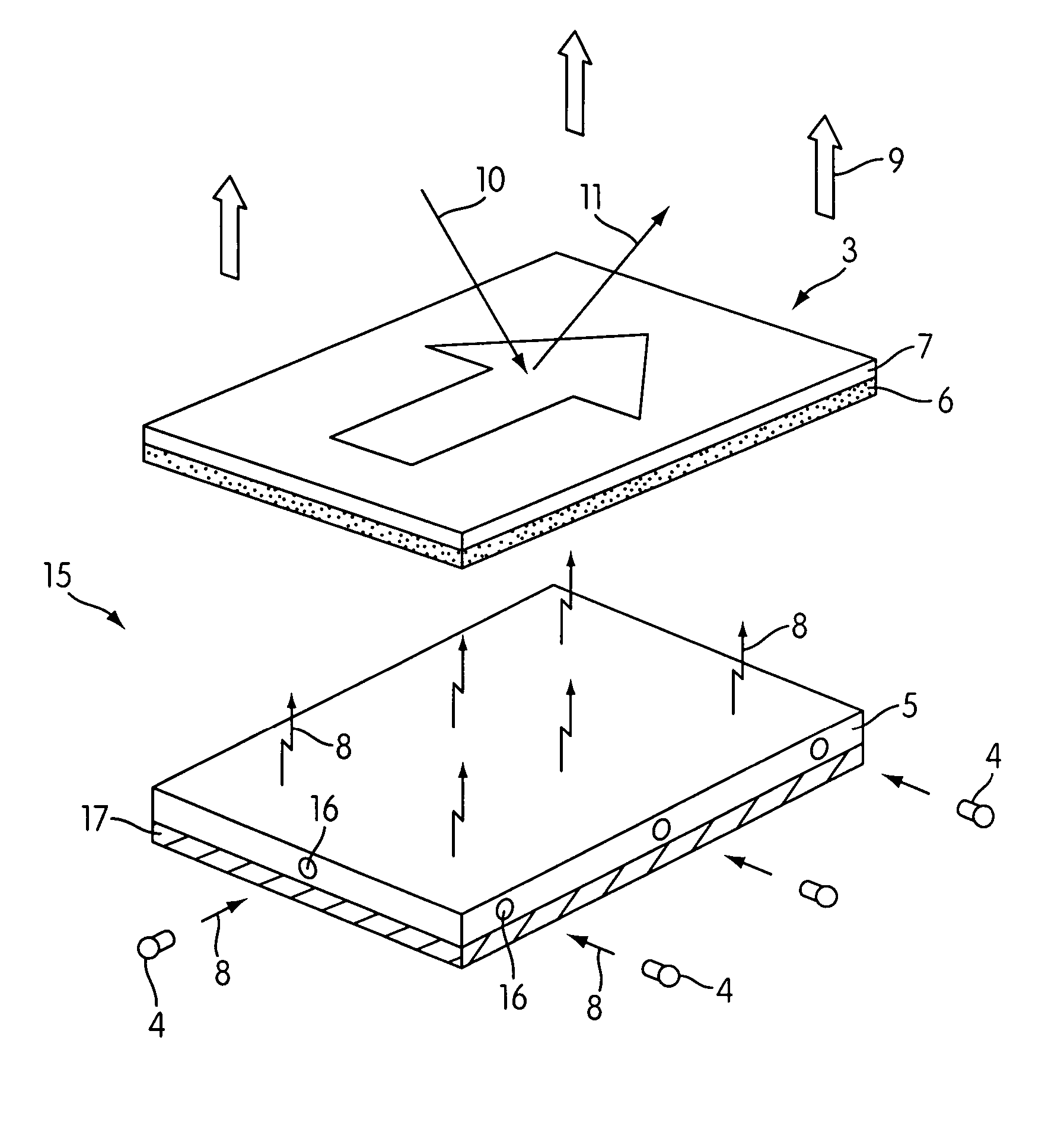
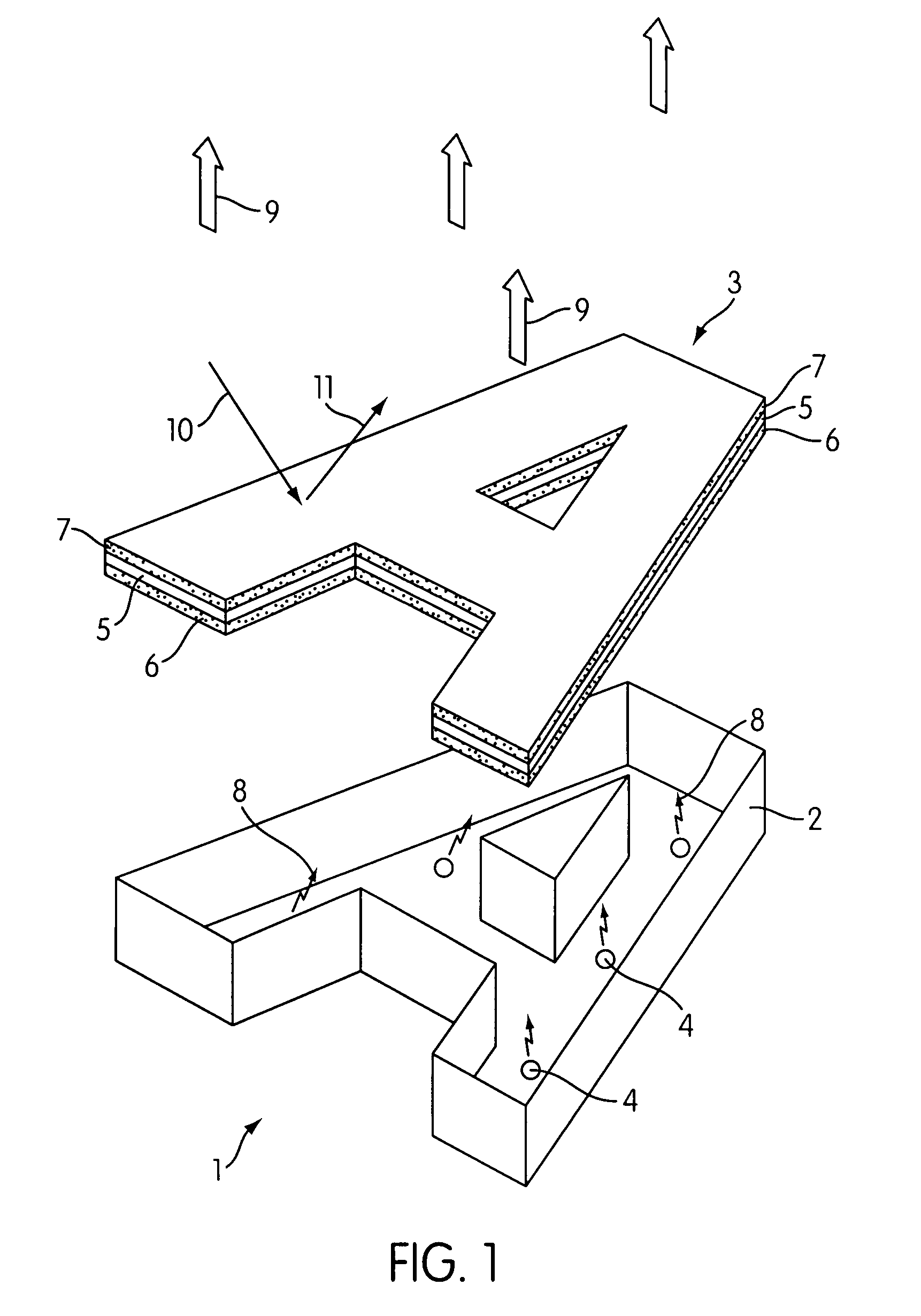
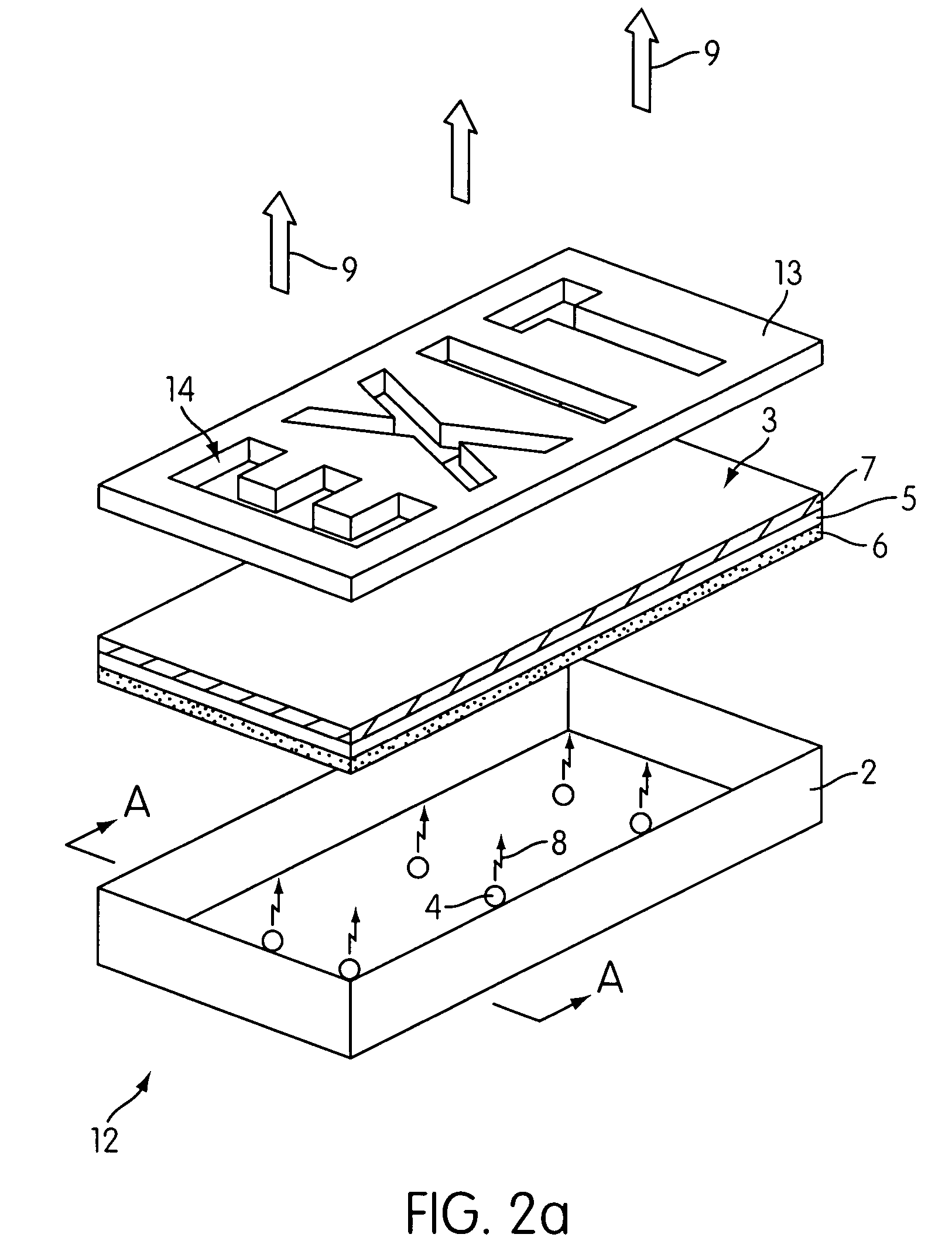
[0040]Referring to FIG. 1 there is shown an exploded perspective view of a backlit light emitting sign 1 in accordance with the invention. In the example illustrated the sign 1 is intended to generate a letter “A” and comprises a light box 2 which is configured in the shape of the letter “A”. The light box can be fabricated from sheet metal, molded from a plastics material or constructed from any other suitable material. The inner surface of the light box preferably includes a light reflective surface to reflect light towards a light emitting display surface 3 of the sign. A number of light emitting diodes (LEDs) 4 are provided within the light box 2 and are preferably blue LEDs which emit blue light in a wavelength range 410 to 470 nm.

[0041]The light emitting display surface 3 is substantially planar in form and is configured in shape to define the letter “A”. The display surface 3 comprises a transparent / translucent substrate 5 such as for example a polycarbonate, polythene, acryl...


PUM


Abstract

A light emitting sign comprising a light emitting display surface including at least one phosphor, and at least one radiation source configured to irradiate the display surface with excitation energy such that the phosphor emits light of a selected color. The sign further comprises a filter which is substantially transparent to light emitted by the display surface, filtering other colors of light. The display surface may be configured into a shape of a character, a symbol, or a device. Alternatively, a mask having at least one window substantially transparent to the emitted light and / or at least one light blocking region may be provided in which the window and / or light blocking region define a character, a symbol, or a device.

Description

BACKGROUND OF THE INVENTION[0001]1. Field of the Invention[0002]The invention relates to light emitting signs and light emitting display surfaces for generating fixed images, graphics, photographic images and characters of a desired color of light. In particular the invention concerns light emitting signs which utilize a semiconductor light emitting diode (LED) and a phosphor (photo luminescent) material to generate a desired color of emitted light. Moreover the invention relates to generating colored light over large surface areas.[0003]2. Description of the Related Art[0004]Light emitting signs / displays, sometimes termed illuminated signs or displays, are used in many applications including: name signs for business premises using fixed graphics and characters, fixed image signs for advertising, emergency signs such as exit signs, traffic signals, road signs for example speed limit, stop, give way (yield) signs, direction indicator signs to name but a few.[0005]A common way to make...

Claims


Application Information

Patent Timeline
Patent Type & Authority Patents(United States)
IPC IPC(8): G09F13/20G09F13/22
CPCG09F13/20G09F13/0404G09F13/22
Inventor LI, YI-QUNDONG, YICARUSO, JAMESEDWARDS, CHARLES O.
Owner INTEMATIX
Why Eureka
Try Eureka