
Sensor pass through assembly

a technology of sensor and assembly, applied in the direction of coupling device connection, installation of lighting conductor, cables, etc., can solve the problems easy damage to wires, and difficulty in organizing and dangling in dangerous conditions, and achieve the effect of low leakage ra

Active Publication Date: 2011-05-10
JETABEAL
View PDF11 Cites 4 Cited by
  • Summary
  • Abstract
  • Description
  • Claims
  • Application Information

AI Technical Summary

Benefits of technology

The assembly provides a robust, airtight seal capable of withstanding high pressures and temperatures, with minimal leakage and ease of maintenance, allowing for quick assembly and disassembly without replacing the entire unit.

Problems solved by technology

A leak, even a small one, could compromise not only the integrity of the conduit, but also the integrity of the entire device.
However, problems exist where wires can be easily damaged exiting extreme temperatures and pressurized environments.
When multiple wires are involved, they are difficult to organize and dangle in dangerous conditions.
The metallic sheets in Cobb; however, cannot seal multiple wires of various diameters simultaneously.
Additionally, since the wire in Cobb deforms the metallic sheets by forming indents, if the wire needs to be repaired or changed, the entire assembly needs to be replaced.
Unfortunately, such a seal can easily loosen and break, particularly when a pressure differential exists.
U.S. Pat. No. 6,918,617 to Nordquist also tries to address the problem by soldering gaps around the wire; however, this makes the set-up difficult to disassemble and reassemble during routine maintenance.

Method used


Image

  • Sensor pass through assembly
  • Sensor pass through assembly
  • Sensor pass through assembly

Examples


Embodiment Construction

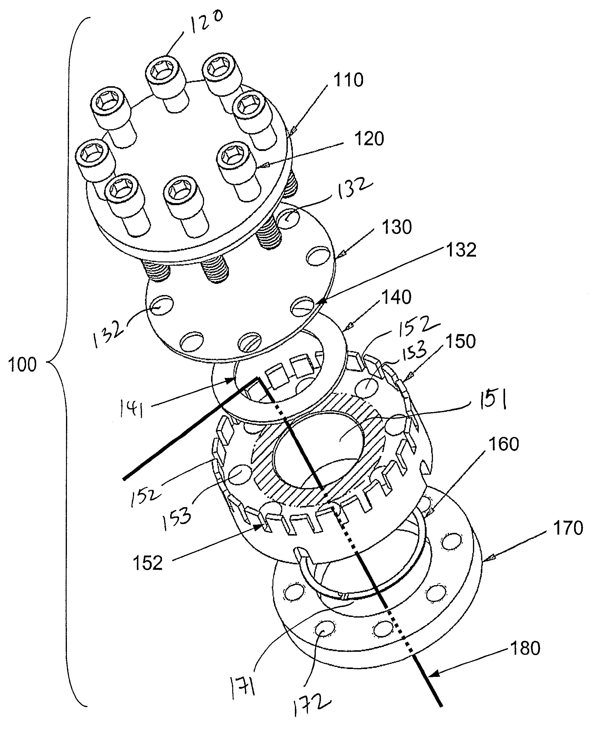
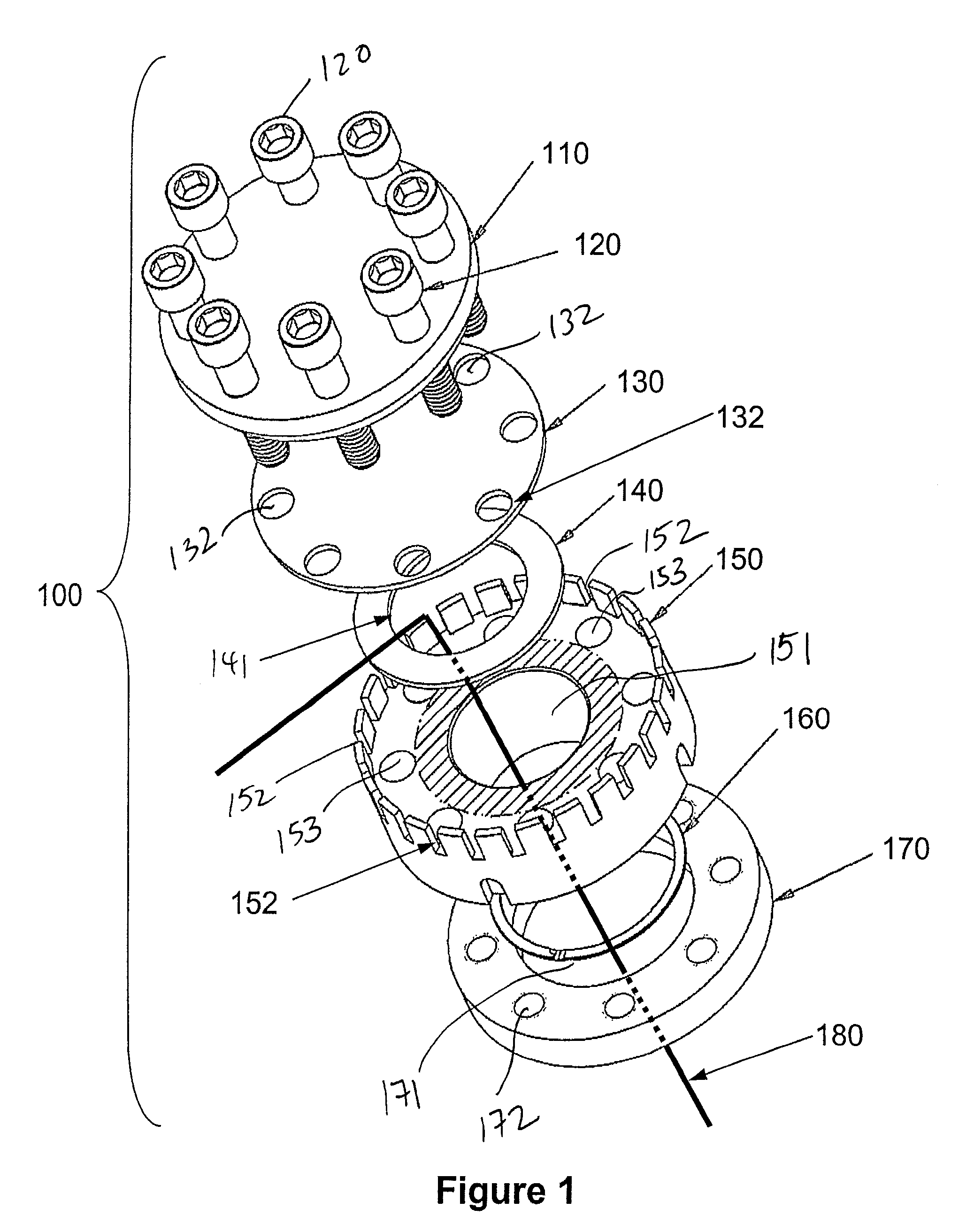
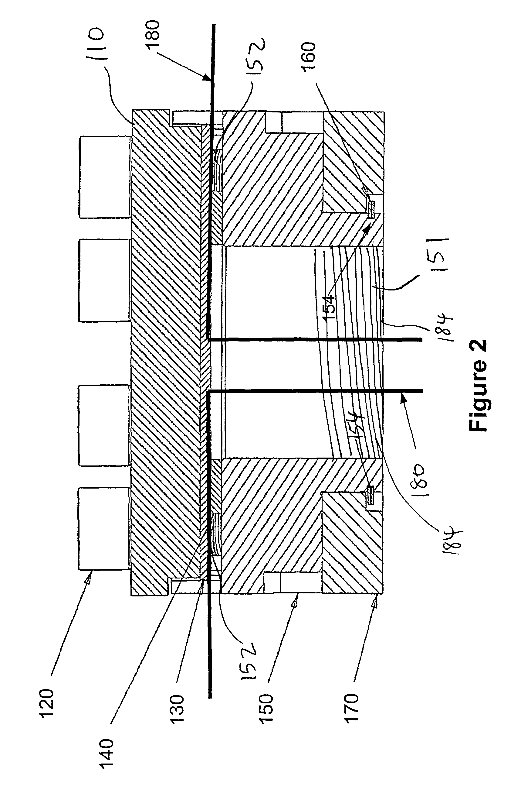
[0024]Referring to the drawings to illustrated preferred embodiments, but not for the purpose of limiting the invention, FIG. 1 illustrates an embodiment of a feed through assembly 100 comprises a cover 110, a first seal 140, a second seal 130, a body 150 and a wire 180. The body receives the wire through an opening on the body. The wire then threads through a first seal to a series of grooves on the body. Then a cover pressures the second seal to the first seal to form a sensor feed through assembly to accommodate the wire. FIGS. 3 and 5 also show other preferred embodiments of the assembly with different configuration of the body and / or seals.

[0025]Body 150, as shown in FIG. 1, generally comprises body opening 151 and a series of grooves 152. Generally, the body is a cylindrical although it can be other shapes such as the ones shown in FIGS. 3 and 5. The body preferably is at least 0.5 inches in height and 0.5 inches in diameter. However it is contemplated that the dimension of th...


PUM


Abstract

Contemplated device, assembly and methods include a sensor feed through assembly that protects and seals a set of wires. The assembly has a body, a first seal, a second seal and a cover. The wires thread through a first opening on the body through a second opening of the first seal and exit orthogonally between the first seal and the second seal. The cover tightens the entire assembly and secures the wires between the two seals. The entire unit can be coupled to other pressurized vessels under different temperatures and pressurized environments.

Description

[0001]This application claims priority to U.S. provisional application Ser. No. 60 / 867,358 filed Nov. 27, 2006 which is incorporated herein by reference in its entirety.FIELD OF THE INVENTION[0002]The field of the invention is a feed-through device for sealing various sensor wires and tubes.BACKGROUND[0003]Seals and gaskets have long been used to seal wires, pipes, tubes, and other conduits to prevent leakage between compartments in a device. An airtight seal is especially important in situations where the conduit connects two environments of drastically different pressures or temperatures. A leak, even a small one, could compromise not only the integrity of the conduit, but also the integrity of the entire device. However, problems exist where wires can be easily damaged exiting extreme temperatures and pressurized environments. When multiple wires are involved, they are difficult to organize and dangle in dangerous conditions.[0004]Sealing units such as the one shown in U.S. Pat. ...

Claims


Application Information

Patent Timeline
Patent Type & Authority Patents(United States)
IPC IPC(8): H01R13/52
CPCH01R13/5208
Inventor HUDLET, STEVEN DOUGLASREUM, REX
Owner JETABEAL
Learn More