
Magnetic recording device and magnetic recording head drive mechanism having a magnetic applying section of a specific length

a technology of magnetic recording head and magnetic recording device, which is applied in the direction of data recording, combination recording, instruments, etc., can solve the problems of increasing the magnetic field required for recording, serious influence on the magnetic bit by the external temperature, and inability to expect a drastic increase in the value of the magnetic field, etc., to achieve high-density magnetic recording

Inactive Publication Date: 2011-05-17
KONICA MINOLTA OPTO
View PDF13 Cites 1 Cited by
  • Summary
  • Abstract
  • Description
  • Claims
  • Application Information

AI Technical Summary

Benefits of technology

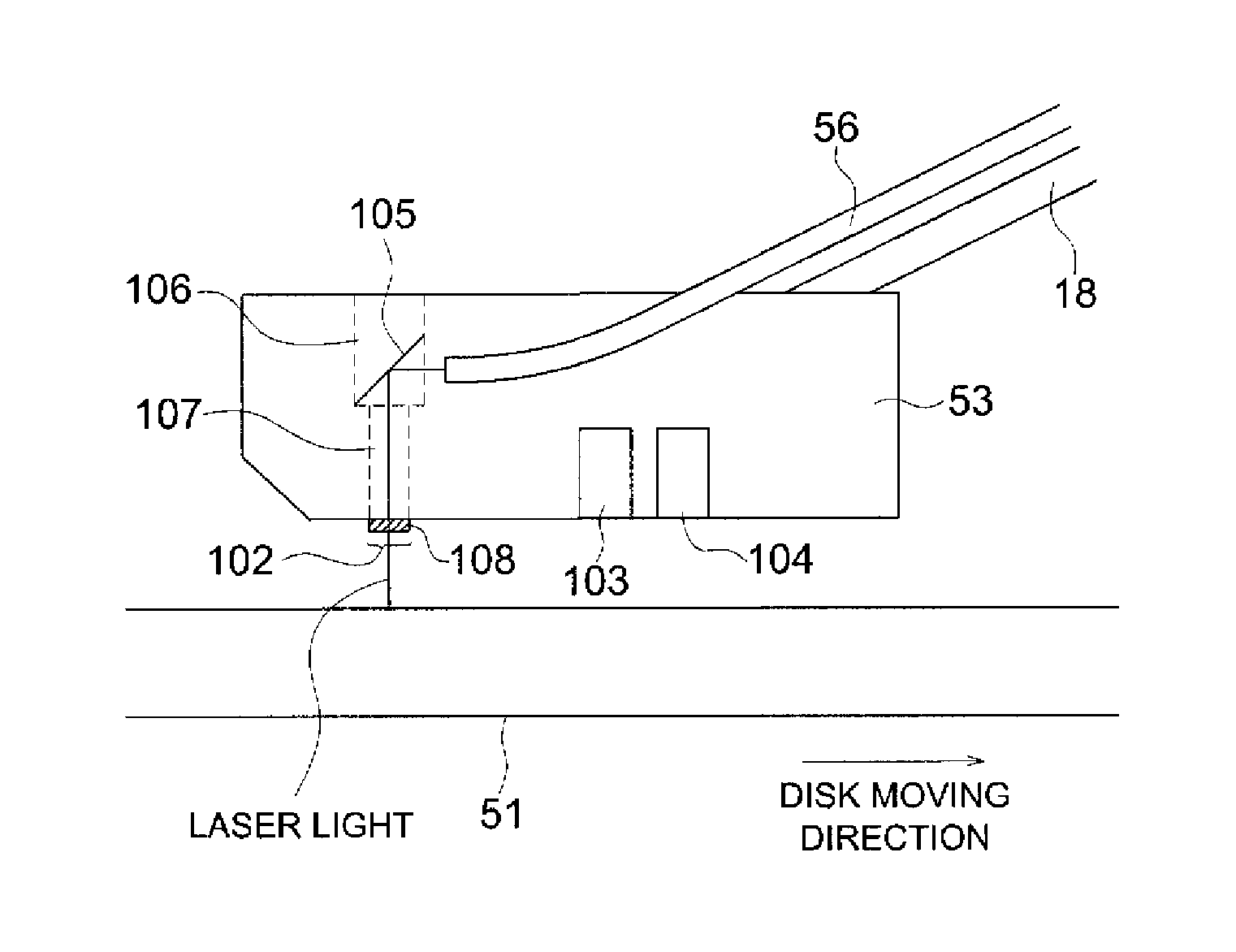
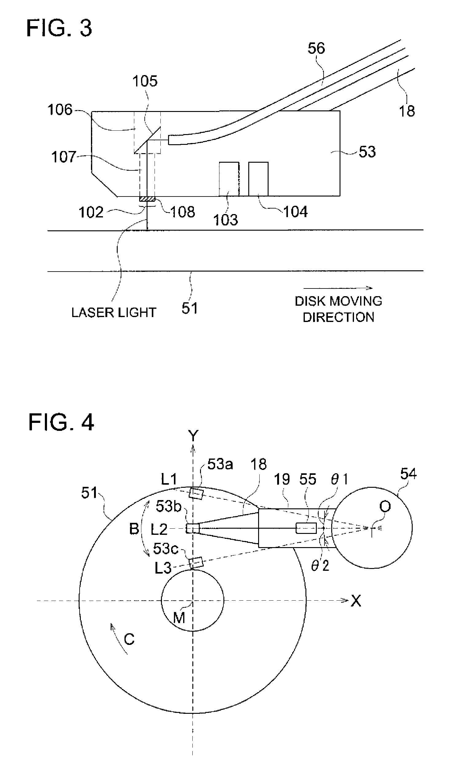
[0042]According to the present invention, when recording on any of the tracks in the radial direction of the magnetic disk, the magnetic applying section traverses the track heated by the heating section. This structure, being a simple structure, ensures high-density magnetic recording, without being affected by the displacement between the heating section and recording element caused when the head is moved along an arc in the radial direction of the magnetic disk.

Problems solved by technology

In the magnetic recording method, a magnetic bit is seriously affected by the external temperature and other factors as the recording density is increased.
However, use of such a recording medium increases the magnetic field required for recording.
The value thereof is already close to the limit of each material, and a drastic increase in this value cannot be expected.
However, in a magnetic recording device using this thermally assisted magnetic recording head, when the thermally assisted magnetic recording head is moved along an arc in the radial direction of the magnetic disk, there will be a change in the angle between the track recorded by the recording element, and the head.
In such a case, the track wherein the recording element passes by is not heated, and a magnetic pattern cannot be formed correctly on the magnetic disk.
According to the method disclosed in Patent Document 1, however, if the distance between the head and magnetic disk is reduced to ensure high-density magnetic recording, the effect of applying a laser beam in a slanting direction will be reduced, and the position immediately below the recording element cannot be heated.
According to the method disclosed in Patent Document 2, if the size of the recording element is reduced to ensure high-density magnetic recording, the formation of the waveguide will be very difficult.

Method used


Image

  • Magnetic recording device and magnetic recording head drive mechanism having a magnetic applying section of a specific length
  • Magnetic recording device and magnetic recording head drive mechanism having a magnetic applying section of a specific length
  • Magnetic recording device and magnetic recording head drive mechanism having a magnetic applying section of a specific length

Examples


Embodiment Construction

[0069]The following describes the embodiments of the present invention with reference to drawings:

[0070][Schematic Configuration of Magnetic Recording Device 100]

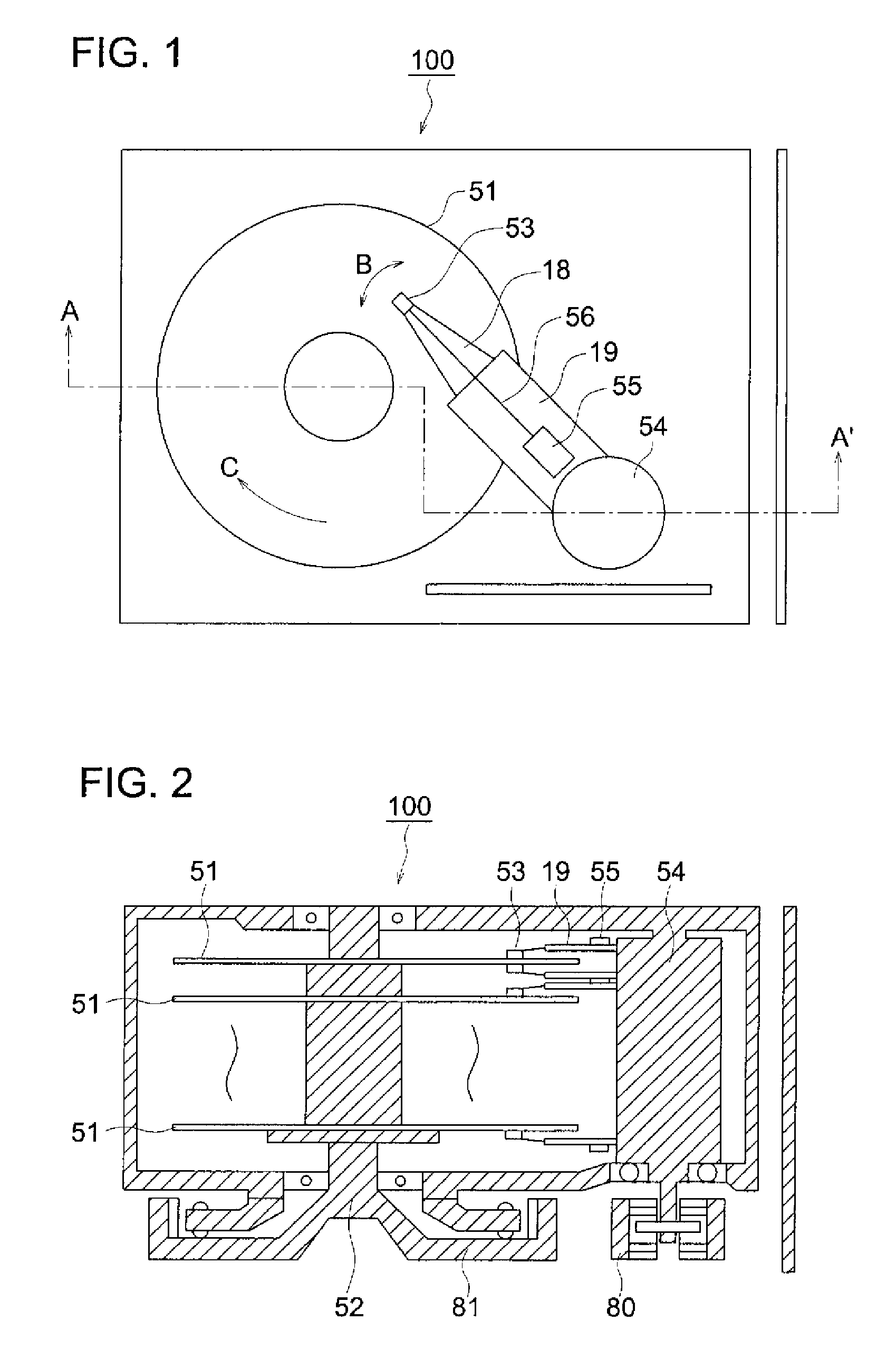
[0071]FIGS. 1 and 2 show the schematic configuration of the magnetic recording device 100 in an embodiment of the present invention. FIG. 1 represents the upper side of the magnetic recording device 100, while FIG. 2 shows the cross section taken along arrow line A-A′.

[0072]The magnetic recording device 100 includes a magnetic disk 51, head 53 for recording and reproducing information, drive shaft 54 and light source 55. As shown in FIG. 1, the head 53 is supported by the suspension section 18 of the arm 19, and the arm 19 is mounted on the drive shaft 54. When the magnetic disk 51 is stopped, the head 53 is biased downward by the suspension section 18, and therefore, the bottom surface of the head 53 is kept in contact with the magnetic disk 51. When the magnetic disk 51 starts to rotate in the direction shown by arrow C, ...


PUM

PropertyMeasurementUnit
distanceaaaaaaaaaa
distanceaaaaaaaaaa
diameteraaaaaaaaaa

Abstract

Provided is a magnetic recording device which can perform high density magnetic recording by simple constitution. The magnetic recording device is provided with a disk driving device for rotating a magnetic disk; a head having a heating section for heating a circular track of the magnetic disk and a recording element for applying a magnetic field modulated by an electric signal to the magnetic disk; and a head drive device for circularly moving the head in the radius direction of the magnetic disk by rotating about a driving shaft. The recording element has a magnetism applying section that traverses any track heated by the heating section in the radius direction of the magnetic disk.

Description

RELATED APPLICATIONS[0001]This application is a National Stage of International Application No. PCT / JP2007 / 070904, filed with the Japanese Patent Office on Oct. 26, 2007, which is based on Japanese Patent Application No. 2006-330430.FIELD OF THE INVENTION[0002]The present invention relates to a magnetic recording device and magnetic recording head.BACKGROUND OF THE INVENTION[0003]In the magnetic recording method, a magnetic bit is seriously affected by the external temperature and other factors as the recording density is increased. This requires use of a recording medium having a high coercive force. However, use of such a recording medium increases the magnetic field required for recording. The upper limit of the magnetic field generated by a recording head is determined by the saturated magnetic flux density. The value thereof is already close to the limit of each material, and a drastic increase in this value cannot be expected. In one of the techniques proposed to solve this pr...

Claims


Application Information

Patent Timeline
Patent Type & Authority Patents(United States)
IPC IPC(8): G11B11/00
CPCG11B5/02G11B5/314G11B5/4866G11B2005/0021G11B11/10554G11B11/1058G11B2005/001G11B11/10536
Inventor SEKINE, KOUJIROUHATANO, HIROSHI
Owner KONICA MINOLTA OPTO
Learn More