Connecting support for holding motor electronics

a technology for connecting supports and motor electronics, which is applied in the direction of electrical apparatus casings/cabinets/drawers, vehicle cleaning, and association of printed circuit non-printed electric components. it can solve the problems of cable damage, complicated production of gear mechanism covers, and replacement of entire gears, so as to achieve quick replacement or installation, low cost

Inactive Publication Date: 2011-05-24
ROBERT BOSCH GMBH
View PDF7 Cites 4 Cited by
  • Summary
  • Abstract
  • Description
  • Claims
  • Application Information

AI Technical Summary

Benefits of technology

[0008]The object of the invention is to specify a solution for the electrical connection of two components which are arranged at a distance from one another on a motor assembly, in particular for connecting control contacts to wiper motors, and for fitting the motor electronics, which solution is distinguished by a low level of outlay on installation and improved functional reliability as compared to the prior art.
[0012]It is advantageous when the supporting structure comprises conductor tracks which connect at least individual elements of the motor electronics to at least one of the components between which the connecting support is arranged. It is also advantageous when the supporting structure comprises conductor tracks which directly connect to one another the components between which the connecting support is arranged. As a result, the supporting structure can replace conventional line connections between said components. It is advantageous and expedient to use one or more printed circuit boards with correspondingly prepared conductor tracks at least as constituent parts of the supporting structure. As an alternative or in addition, it may be advantageous when the supporting structure comprises a plastic part with injection-molded conductive strips or injection-molded cables. The connecting support can likewise additionally be used as a guidance aid for the cables to be laid between the connected components.
[0013]It is advantageous when the connecting support is connected to at least one housing part of the motor assembly. The connection to the housing part ensures adequate fixing of position and fixing of the entire connecting support, particularly when the supporting structure is connected to the housing of the motor assembly.
[0015]In particular, the above-mentioned adapter can be used to match the connection system to specific customer wishes with a low level of outlay, without having to change the plugging slot on the motor assembly. If the connecting support is connected to the adapter, this produces a component which has all the functions of the system according to the invention and can be quickly replaced or installed. Particularly in this case, it is advantageous when the connecting support, in particular the supporting structure, is releasably connected to at least one housing part of the motor assembly by means of connecting elements. The ability to exchange the connecting support additionally permits quick replacement of the contained motor electronics, this being advantageous in the event of a fault or when adaptations are required.
[0016]If it is not necessary to change over the connecting support quickly, said connecting support may be adhesively bonded to at least one housing part of the motor assembly, this providing a particularly robust design which also virtually excludes the supporting structure from being accidently engaged in from behind, and thus the damage associated with this. In order to protect the motor electronics, it is advantageous when at least some of the motor electronics are located beneath a cover. This cover may advantageously be designed as an electrical shield.

Problems solved by technology

The variant with metal strips running in the gear mechanism cover complicates production of the gear mechanism cover and, when adaptations are needed or there are defects in the contact-connection to the control contacts, always requires the replacement of the entire gear mechanism cover.
The variant with cables which run freely across the outside of the motor assembly is associated, in particular, with the risk of damage to the cables.

Method used


Image

  • Connecting support for holding motor electronics
  • Connecting support for holding motor electronics
  • Connecting support for holding motor electronics

Examples


Embodiment Construction

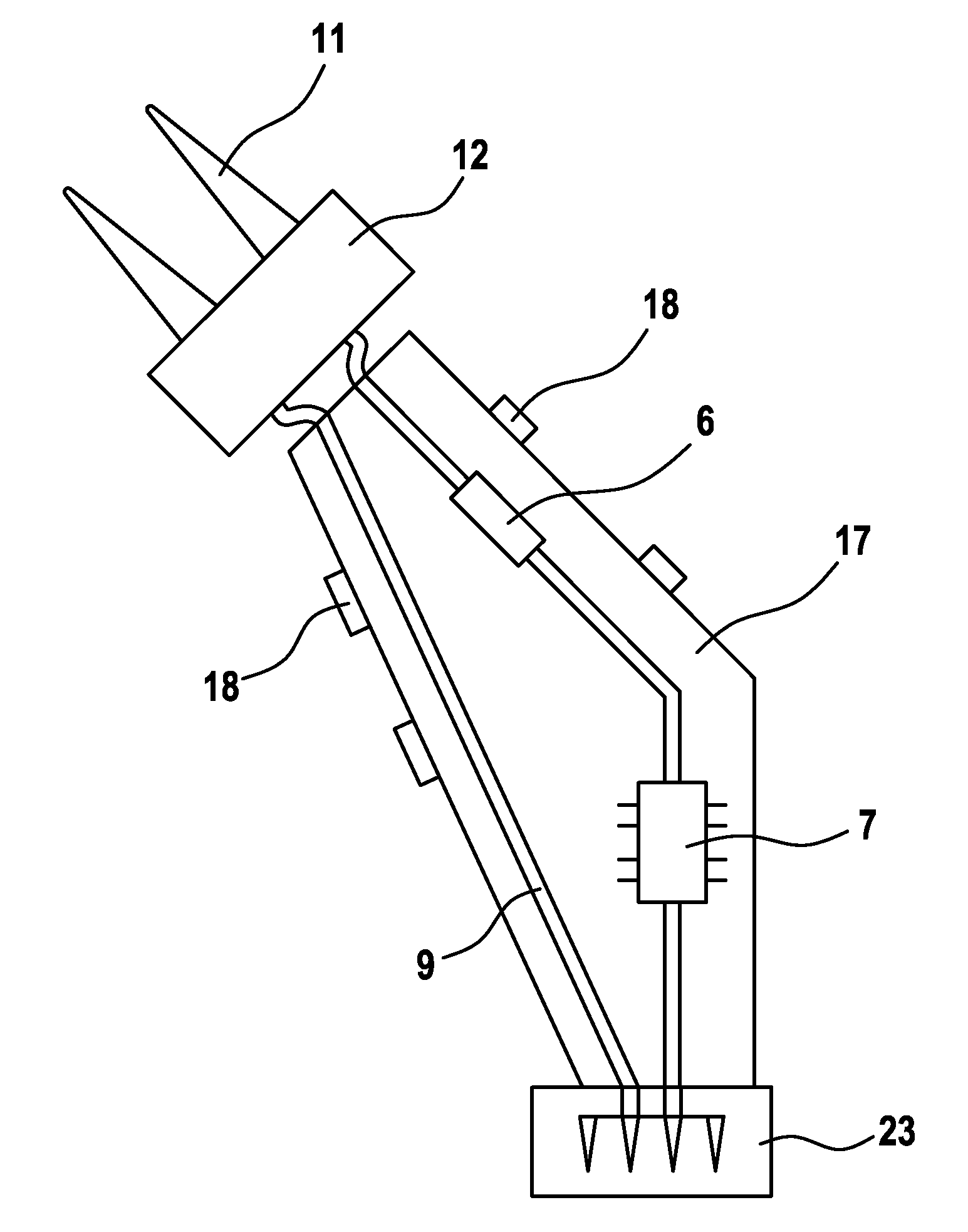
[0022]FIG. 1 shows the basic structure of a connecting support 1 according to the invention. Said connecting support is arranged on the outside of a motor assembly 2 and is located between two components 3 and 4 which are arranged at a distance from one another and whose positions in relation to the motor subassembly 2 are fixed. The connecting support 1 comprises a supporting structure 5 to which individual elements of the motor electronics 6, 7 are fixed. The connecting support 1 also comprises electrical connecting means 8, 9 by means of which the adjoining components 3, 4 are electrically connected to one another. This electrical connection can be realized both via the motor electronics 6, 7 and by direct connections with the aid of electrical lines 9. In the case of the direct connections, the connecting support 1 forms a supporting element which defines the geometric profile of the electrical line 9.

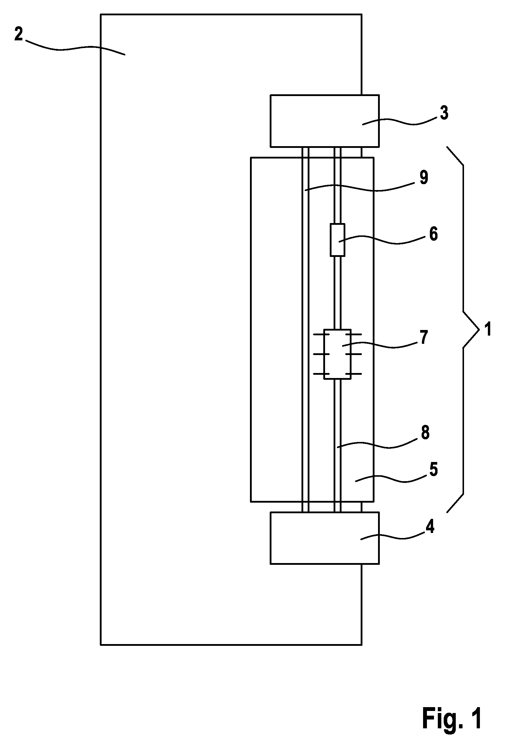
[0023]FIG. 2 shows a connecting support 1 according to the invention on the ho...


PUM


Abstract

The invention relates to a connecting support (1) for holding motor electronics on a motor subassembly (2), the connecting support being located between at least two components (3, 4) arranged at a distance from each other on the motor subassembly (2), wherein the connecting support (1) has means (8, 9) by means of which said components (3, 4) are electrically connected to each other, and wherein the connecting support (1) has a supporting structure (5) to which at least individual elements (6, 7) of the motor electronics are fastened.

Description

BACKGROUND OF THE INVENTION[0001]The invention relates to a connecting support for holding motor electronics, as can be used, in particular, on wiper motors in vehicles.[0002]An established way of using electric motors as drives of wiper systems is embedding an electric motor in a complex assembly, called motor assembly in the text which follows, which, in addition to the actual motor, comprises gear mechanism components, housing parts, fixing means, electrical connection means and motor electronics. In this case, the electrical connection means are frequently arranged in the immediate vicinity of the motor parts with which contact is to be made, in order to be able to realize short conduction paths.[0003]In the interests of simplified connection, the connection plugs used are frequently designed such that the motor assembly is fully ready for operation when said connection plugs are connected. Consequently, components with which contact is to be made and which are arranged at a dis...

Claims


Application Information

Patent Timeline
Patent Type & Authority Patents(United States)
IPC IPC(8): H02K11/00
CPCB60S1/08B60S1/166H05K1/18H05K5/00
Inventor PAULI, STEPHANBOHN, ROLAND
Owner ROBERT BOSCH GMBH
Why Eureka
Try Eureka