Hand tool rack

a tool rack and hand technology, applied in the field of hand tool racks, can solve the problems of limited space available for inserting hand tools, and achieve the effect of easy mounting on the wall and adjustment of the distance between two adjacent hand tools

Active Publication Date: 2011-05-31
KAO JUI CHIEN
View PDF24 Cites 43 Cited by
  • Summary
  • Abstract
  • Description
  • Claims
  • Application Information

AI Technical Summary

Benefits of technology

[0007]The main objective of the present invention is to provide a hand tool rack that can be mounted on a wall easily and a distance between two adjacent hand tools can be adjusted.

Problems solved by technology

However, the clamping elements are firmly mounted on the rack and cannot be moved to maximize utility of available space on the rack and when the rack is mounted on the wall, only limited space is available for inserting hand tools into the through holes in the clamping elements.

Method used


Image

  • Hand tool rack
  • Hand tool rack
  • Hand tool rack

Examples


Embodiment Construction

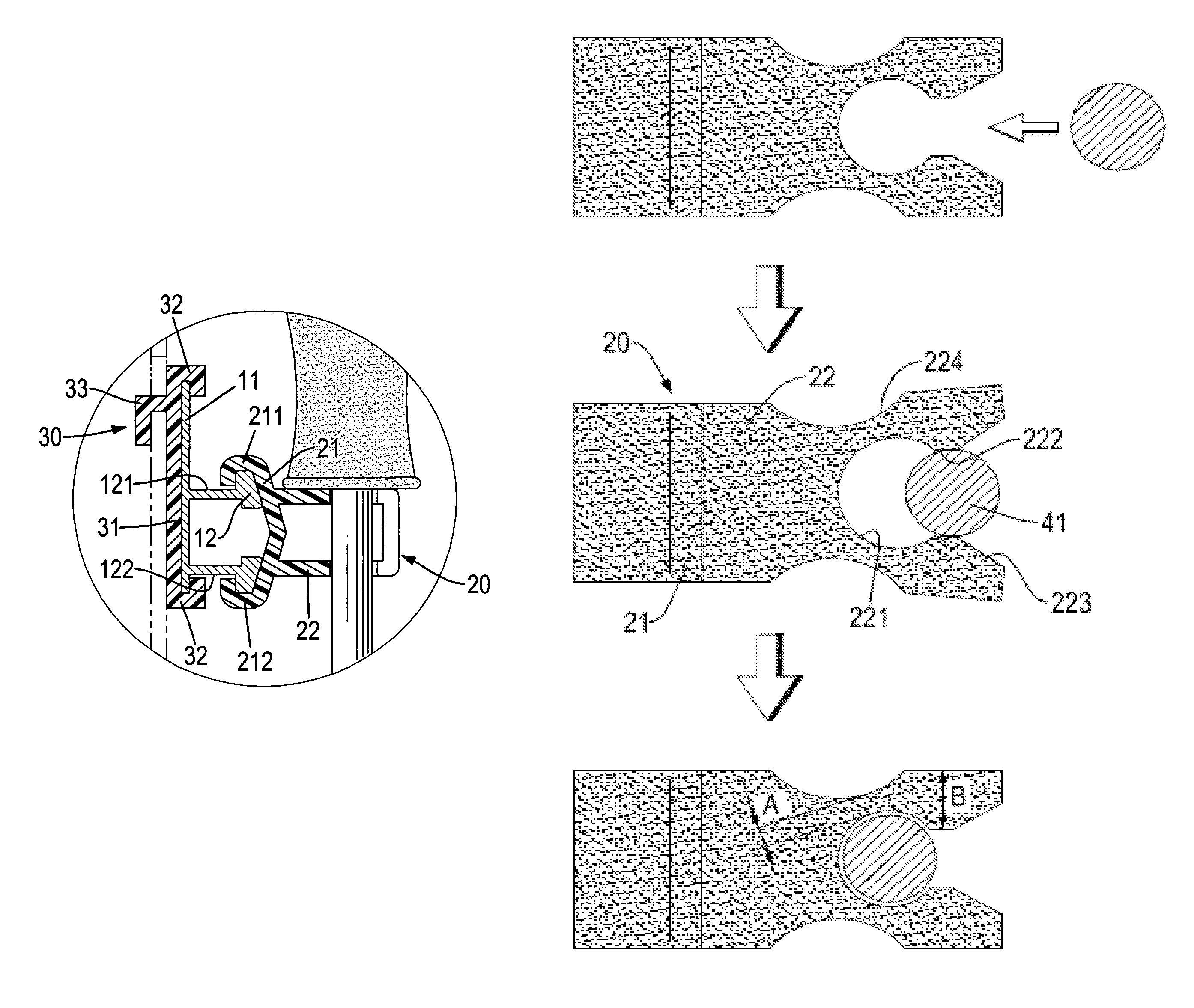
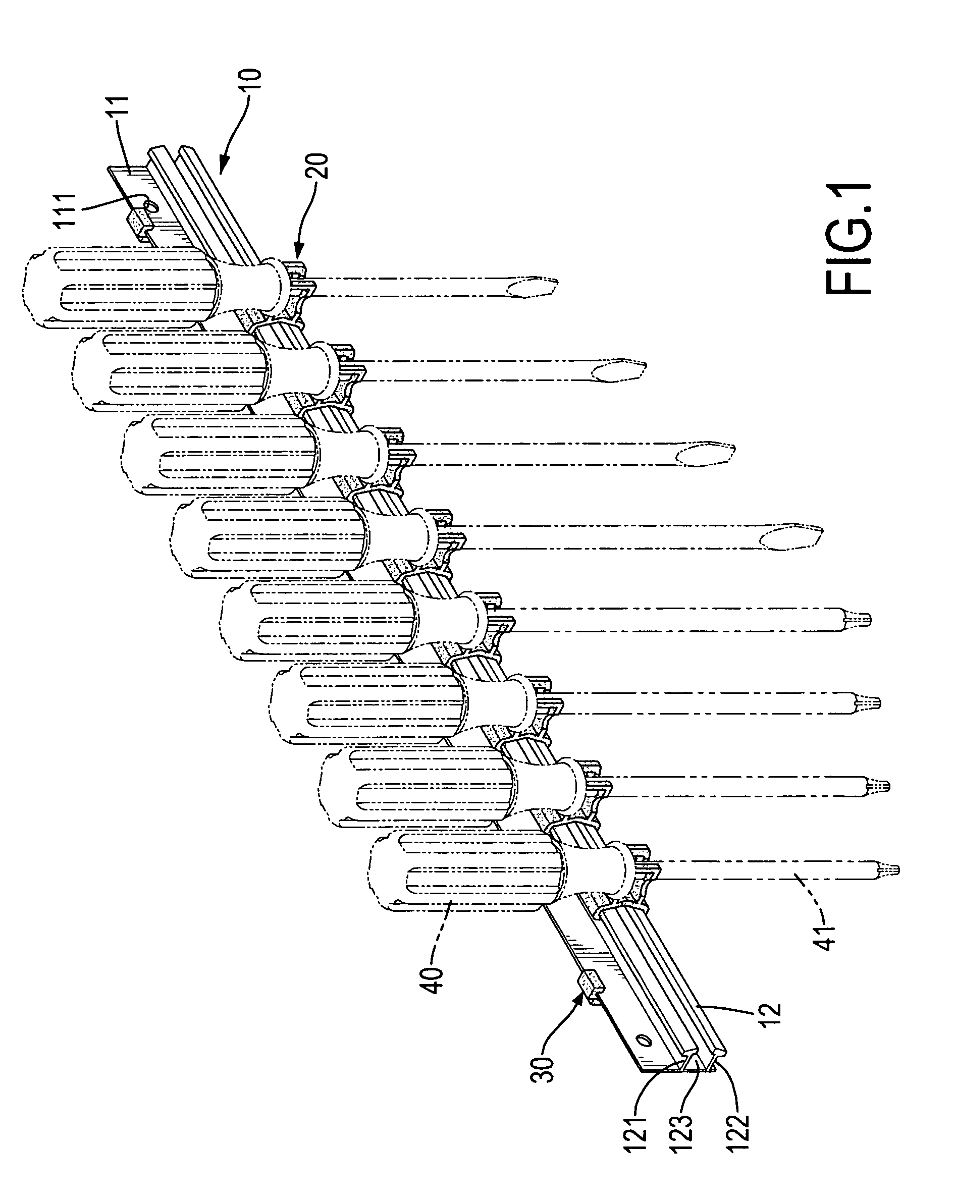
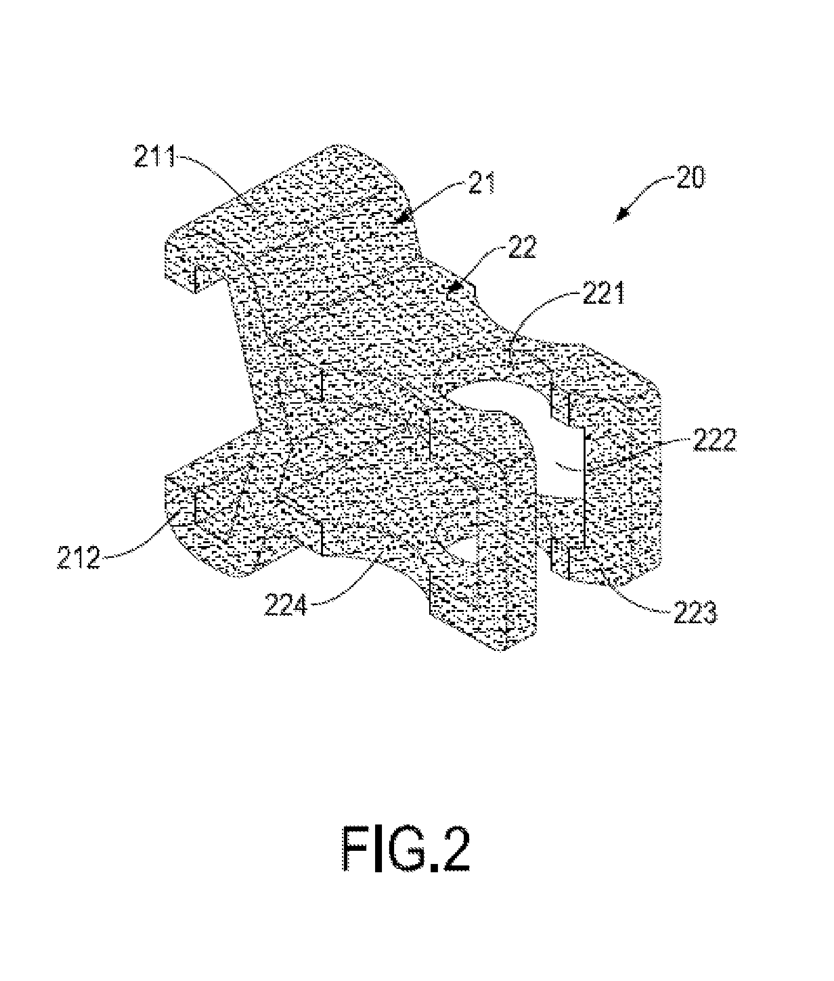
[0024]With reference to FIGS. 1 to 4B, 9, 11 and 12, a hand tool rack in accordance with the present invention for holding hand tools (40) has an elongated base bracket (10), multiple clamping elements (20, 20A, 20B) and two hangers (30).

[0025]The base bracket (10) may be hung on a surface such as a wall or a tool cart and has a baseboard (11, 11B) and a rail bracket (12, 12B).

[0026]The baseboard (11, 11B) may be elongated and has a front surface, a rear surface, a top edge, a bottom edge, two ends and two bolt holes (111, 111B). The bolt holes (111, 111B) are respectively formed through the surfaces of the baseboard (11, 11B) near the ends of the baseboard (11, 11B).

[0027]The rail bracket (12, 12B) is longitudinally formed on and protrudes from the front surface of the baseboard (11, 11B) and has an upper rail (121, 121B), a lower rail (122, 122B) and a channel (123). The upper rail (121, 121B) is longitudinally formed on and protrudes from the front surface of the baseboard (11, 1...


PUM


Abstract

A hand tool rack has an elongated base bracket and multiple clamping elements. The base bracket has a baseboard and a rail bracket. The rail bracket is formed on and protrudes from the baseboard. The clamping elements are movably mounted on the rail bracket and each clamping element has a clamping arm and a tool mount. The clamping arm is slidably mounted and clamps on the rail bracket and has two holders. The tool mount is formed on and protrudes from the clamping arm and has a tool hole, a mounting slit and two recesses. The tool hole is formed through an upper surface and a lower surface of the tool mount. The mounting slit is formed through the upper surface, a front surface and the lower surface of the tool mount and communicates with the tool hole. The recesses are respectively formed in the sidewalls of the tool mount.

Description

BACKGROUND OF THE INVENTION[0001]1. Field of the Invention[0002]The present invention relates to a tool rack, and more particularly to a hand tool rack that can be mounted on a wall easily and a distance between two adjacent hand tools can be adjusted.[0003]2. Description of the Prior Art[0004]A conventional hand tool rack is suspended on a wall, so that hand tools can be organized to facilitate work efficiency and prevent loss of tools. The conventional hand tool rack is provided with an elongated rack adapted for connection to a wall and multiple clamping elements firmly formed on the elongated rack. Each clamping element defines a through hole to hold a shank of the hand tool.[0005]However, the clamping elements are firmly mounted on the rack and cannot be moved to maximize utility of available space on the rack and when the rack is mounted on the wall, only limited space is available for inserting hand tools into the through holes in the clamping elements.[0006]To overcome the s...

Claims


Application Information

Patent Timeline
Patent Type & Authority Patents(United States)
IPC IPC(8): A47F7/00
CPCB25H3/04A47F5/0846
Inventor KAO, JUI-CHIEN
Owner KAO JUI CHIEN
Why Eureka
Try Eureka