Pipe coupling having movable gripping bodies

a gripping body and pipe technology, applied in the field of couplings, can solve the problems of limited value of power tools and inability to use power tools which cause electrical sparking in environments

Active Publication Date: 2011-05-31
VICTAULIC
View PDF35 Cites 86 Cited by
  • Summary
  • Abstract
  • Description
  • Claims
  • Application Information

AI Technical Summary

Benefits of technology

[0011]Another embodiment of the pipe coupling according to the invention comprises a plurality of segments connectable end-to-end. The segments surround a central space. Each segment has first and second arcuate grooves in spaced relation facing the central space. Connection members are positioned at opposite ends of each of the segments for adjustably connecting the segments to one another. The connection members are adjustably tightenable for drawing the segments toward one another. First and second reaction surfaces are positioned at opposite ends of each coupling segment in spaced relation to one another. The reaction surfaces face the central space. First and second gripping bodies are positioned between the segments at opposite ends thereof. Each of the gripping bodies has first and second arcuate grooves positioned in spaced relation. The grooves face the central space. Each of the gripping bodies has a plurality of contact surfaces positioned in facing relation with the reaction surfaces. Each of the contact surfaces is engaged with one of the reaction surfaces on each of the segments. First and second retainers are received within the grooves of the couplings. Each of the retainers comprises an annular band having a plurality of teeth extending radially inwardly. Each annular band is split so as to permit radial motion of the teeth when the band is radially compressed. The first retainer is received within the first grooves in the coupling segments and the gripping bodies and the second retainer is received within the second grooves in the coupling segments and the gripping bodies. The teeth of the first retainer are angularly oriented toward the teeth of the second retainer, and the teeth of the second retainer are angularly oriented toward the teeth of the first retainer. Adjustable tightening of the connection members draws the coupling segments together. The contact surfaces interact with the reaction surfaces to move the gripping bodies radially inwardly for compressing the retainers into engagement with the pipe elements. Preferably, the reaction surfaces extend in a tangential direction of the segments.

Problems solved by technology

Power tools are of limited value, however, where no source of electrical power or compressed air is available, even those tools which are battery operated.
Furthermore, power tools which cause electrical sparking may not be used in environments, such as mines, where explosive conditions may exist.

Method used


Image

  • Pipe coupling having movable gripping bodies
  • Pipe coupling having movable gripping bodies
  • Pipe coupling having movable gripping bodies

Examples


embodiment 10

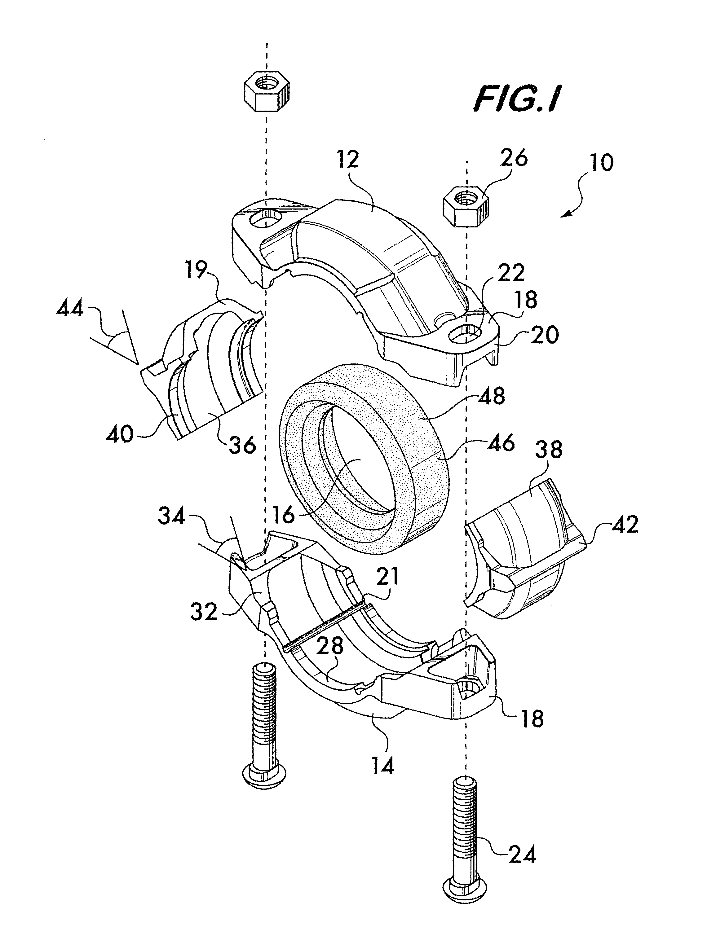
[0027]FIG. 1 shows an exploded isometric view of a coupling embodiment 10 according to the invention. Coupling 10 comprises a plurality of segments 12 and 14. Segments 12 and 14 are connectable end-to-end to surround a central space 16. Connection of the segments is effected by connection members 18 positioned at opposite ends of each of the segments 12 and 14. In this embodiment, the connection members comprise projections 20 which extend outwardly from the ends of the segments. Projections 20 have apertures 22 adapting them to receive fasteners, such as bolts 24 and nuts 26. The fasteners are adjustably tightenable and cooperate with the projections 20 for drawing the segments 12 and 14 toward the central space 16 upon tightening.

[0028]Each segment has a pair of arcuate surfaces 28. Surfaces 28 are positioned in spaced relation to one another and face the central space 16. The arcuate surfaces engage and retain pipe elements 30 (see FIG. 4) when the fasteners connecting projection...

embodiment 11

[0035]FIG. 4A illustrates another embodiment 11 of a coupling according to the invention. In this embodiment, the contact surfaces 42 on the gripping bodies 36 and 38 have a convex shape. This permits them to engage the reaction surfaces 32 tangentially when the segments 12 and 14 are drawn toward one another, resulting in reaction forces which cause motion of the gripping bodies toward the central space. The reaction surfaces 32 are angularly oriented. FIG. 4B shows another embodiment 13 wherein the reaction surfaces 32 have a convex shape and the contact surfaces 42 are angularly oriented. This again allows for tangential engagement between the reaction surfaces and the contact surfaces, resulting in reaction forces which cause motion of the gripping bodies toward the central space as the segments 12 and 14 are drawn toward each other.

embodiment 50

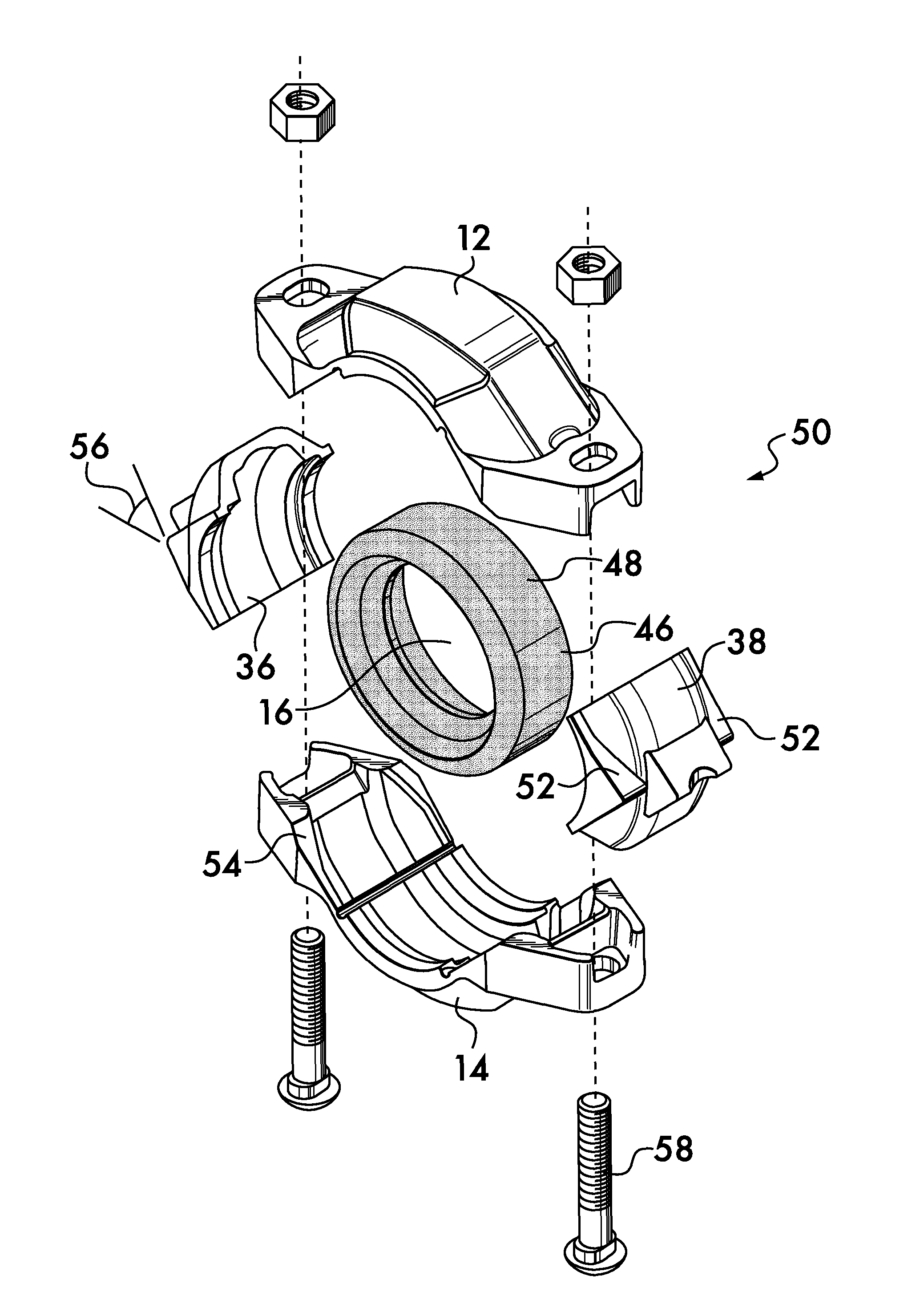
[0036]FIG. 5 shows an isometric exploded view of another coupling embodiment 50 according to the invention. Coupling 50 has gripping bodies 36 and 38 with contact surfaces 52 positioned on opposite sides of the gripping bodies. Again, the contact surfaces are angularly oriented with respect to the connection members 18 and interface with reaction surfaces 54 positioned on the connection members 18. Orientation angles 56 for the contact surfaces from about 30° to about 60° are advantageous for this coupling design. It is preferred that the orientation angle of the reaction surfaces 54 be approximately the same as the contact surfaces as shown in FIG. 8.

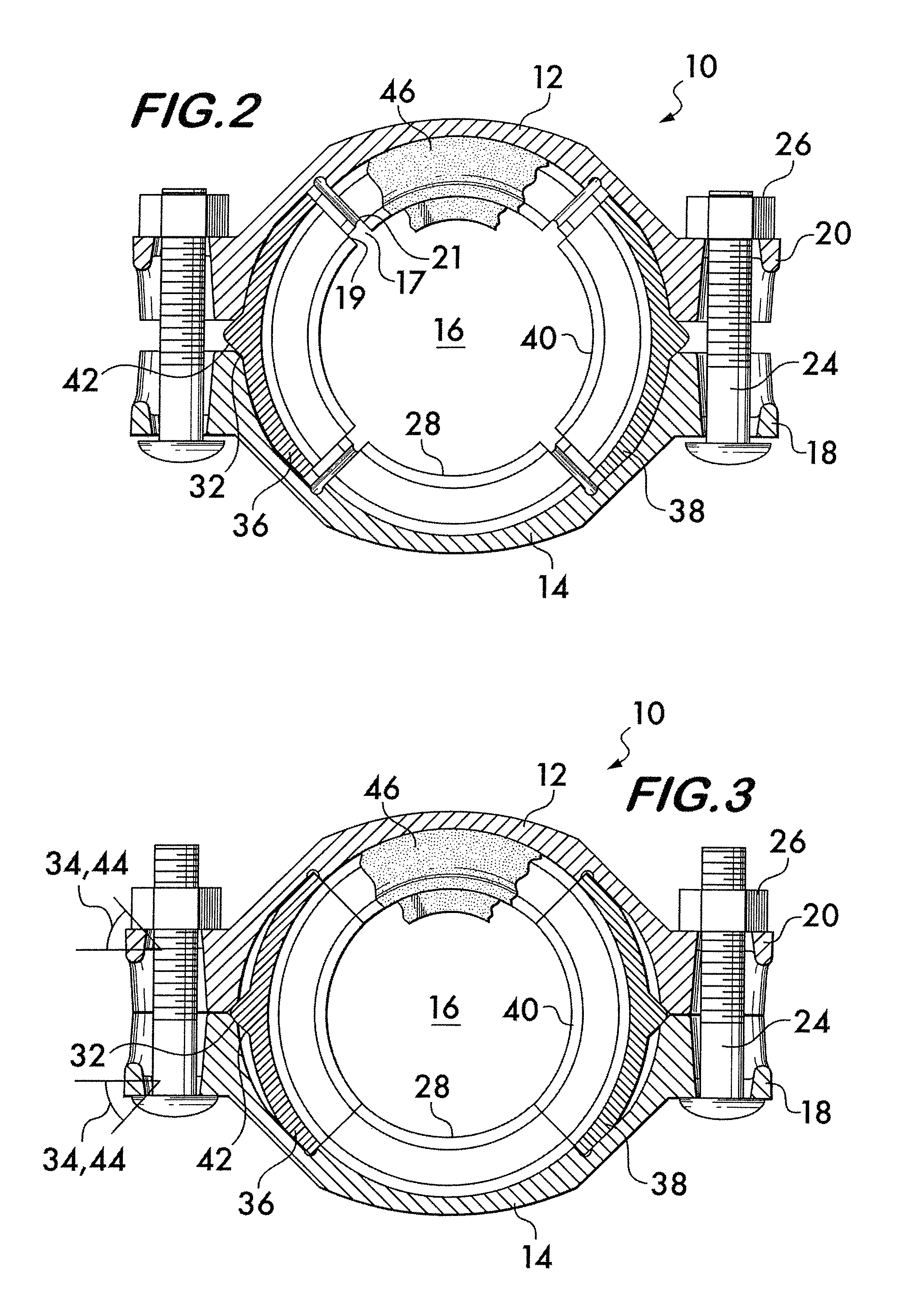
[0037]Upon assembly of the coupling 50, a seal 46 is captured within the central space 16 by the segments 12 and 14 and the gripping bodies 36 and 38. Seal 46 ensures that the coupling 50 provides a fluid-tight joint between pipe ends. The seal is sized so that, in an undeformed state, its outer circumference 48 supports the segments 1...


PUM


Abstract

A coupling for securing pipe elements together in end-to-end relation has segments joined end-to-end by adjustable connection members. The segments surround a central space which receives the pipe elements. One or more gripping bodies are captured between the segments. The gripping bodies are arranged opposite to each other. The segments have angularly oriented reaction surfaces on the connection members. The gripping bodies have angularly oriented contact surfaces which interface with the reaction surfaces. When the segments are drawn toward each other by the connection members, interaction between the reaction surfaces and the contact surfaces forces the gripping bodies radially inwardly. Inwardly facing arcuate surfaces on the segments and the gripping bodies engage and retain the pipe elements.

Description

CROSS-REFERENCE TO RELATED APPLICATION[0001]This application is based on and claims priority to U.S. Provisional patent application No. 60 / 938,003, filed May 15, 2007.FIELD OF THE INVENTION[0002]This invention relates to couplings for joining pipe elements in end-to-end relationship.BACKGROUND OF THE INVENTION[0003]Mechanical couplings for joining pipe elements end-to-end find widespread use throughout a broad spectrum of industries such as the chemical industry, the petroleum industry and mining, as well as in municipal water service and fire suppression systems for buildings and other structures.[0004]An example of a prior art coupling currently in use is provided in U.S. Pat. No. 7,086,131, which discloses a coupling having a pair of coupling segments joined end-to-end by fasteners received in lugs at each end of the segments. A sealing member is positioned between the segments. The coupling is pre-assembled at the factory. The segments are designed and sized to receive pipe elem...

Claims


Application Information

Patent Timeline
Patent Type & Authority Patents(United States)
IPC IPC(8): F16L23/00
CPCF16L17/04F16L21/065F16L21/08F16L23/08F16L23/18Y10T29/49948Y10T29/49963Y10T29/53987Y10T29/49947F16L39/00
Inventor DOLE, DOUGLAS R.PORTER, MICHAEL V.SIPOS, TORREY G.
Owner VICTAULIC
Why Eureka
Try Eureka