
Packaging and applicator device

a technology of applicator and brush, which is applied in the direction of brushes, packaged goods types, applications, etc., can solve the problems of insufficient impurity of brush bundles and the risk of excess composition being delivered onto the applicator element, and achieve the effect of slowing down the flow of composition and improving the impregnation of bristles

Inactive Publication Date: 2011-05-31
LOREAL SA
View PDF17 Cites 5 Cited by
  • Summary
  • Abstract
  • Description
  • Claims
  • Application Information

AI Technical Summary

Benefits of technology

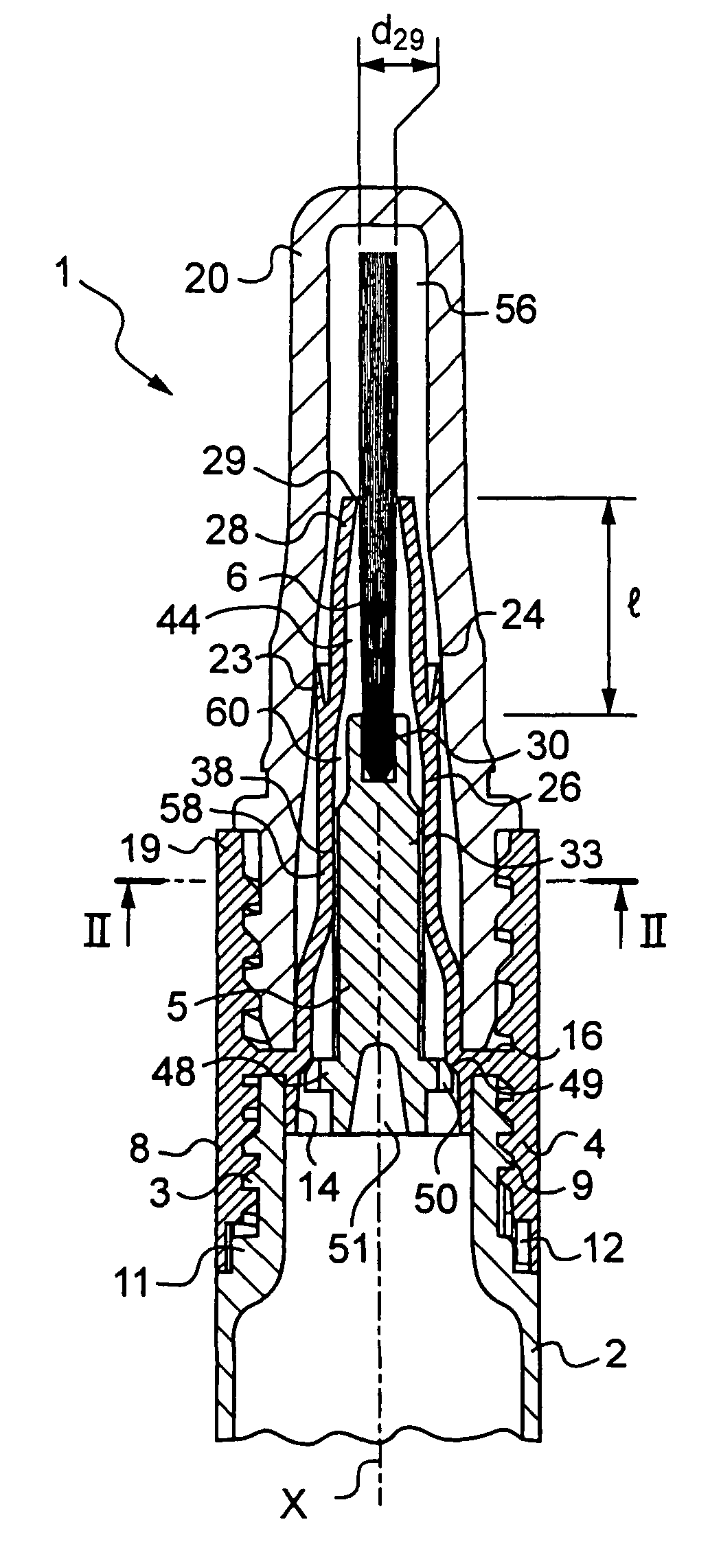
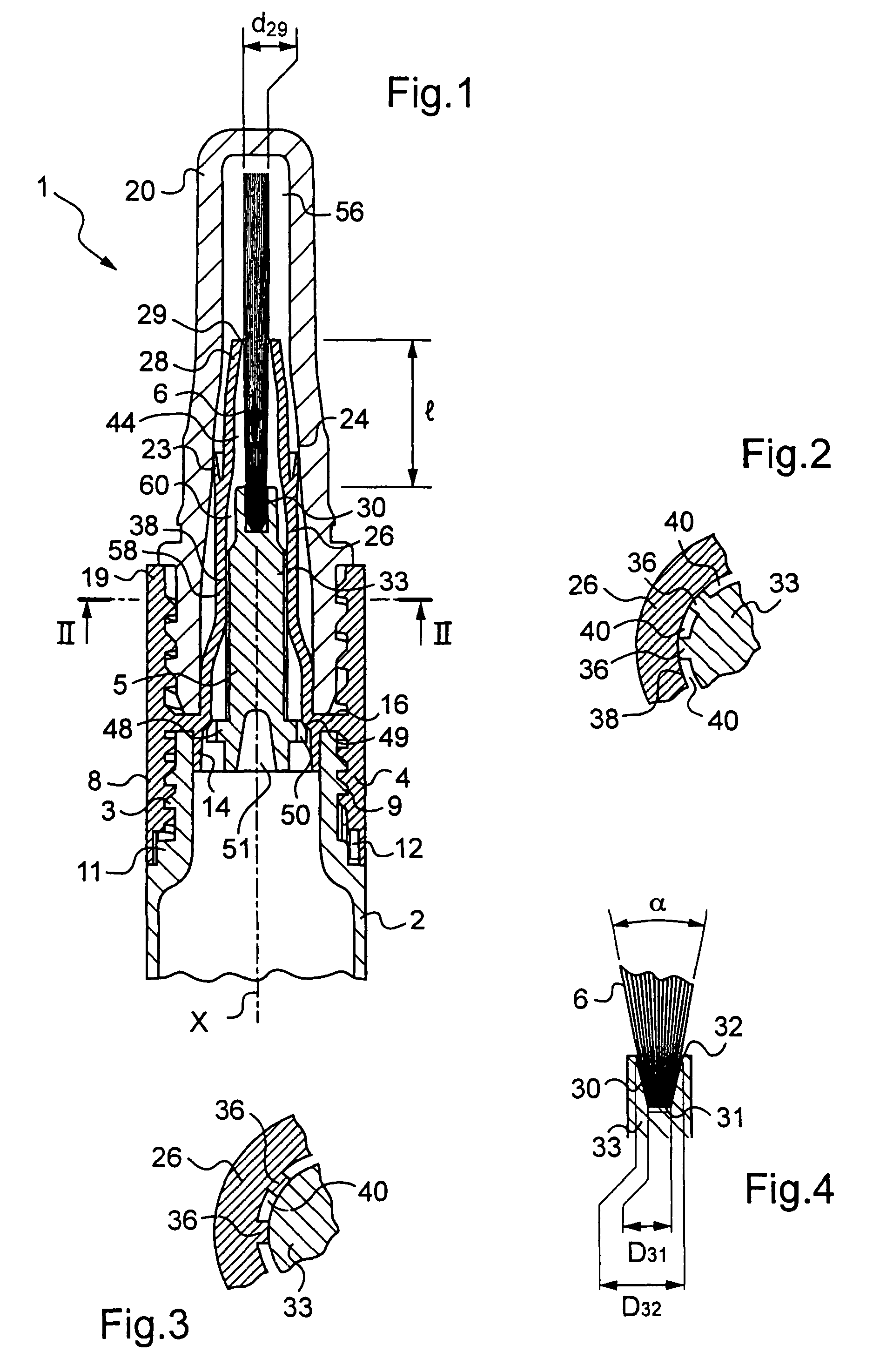
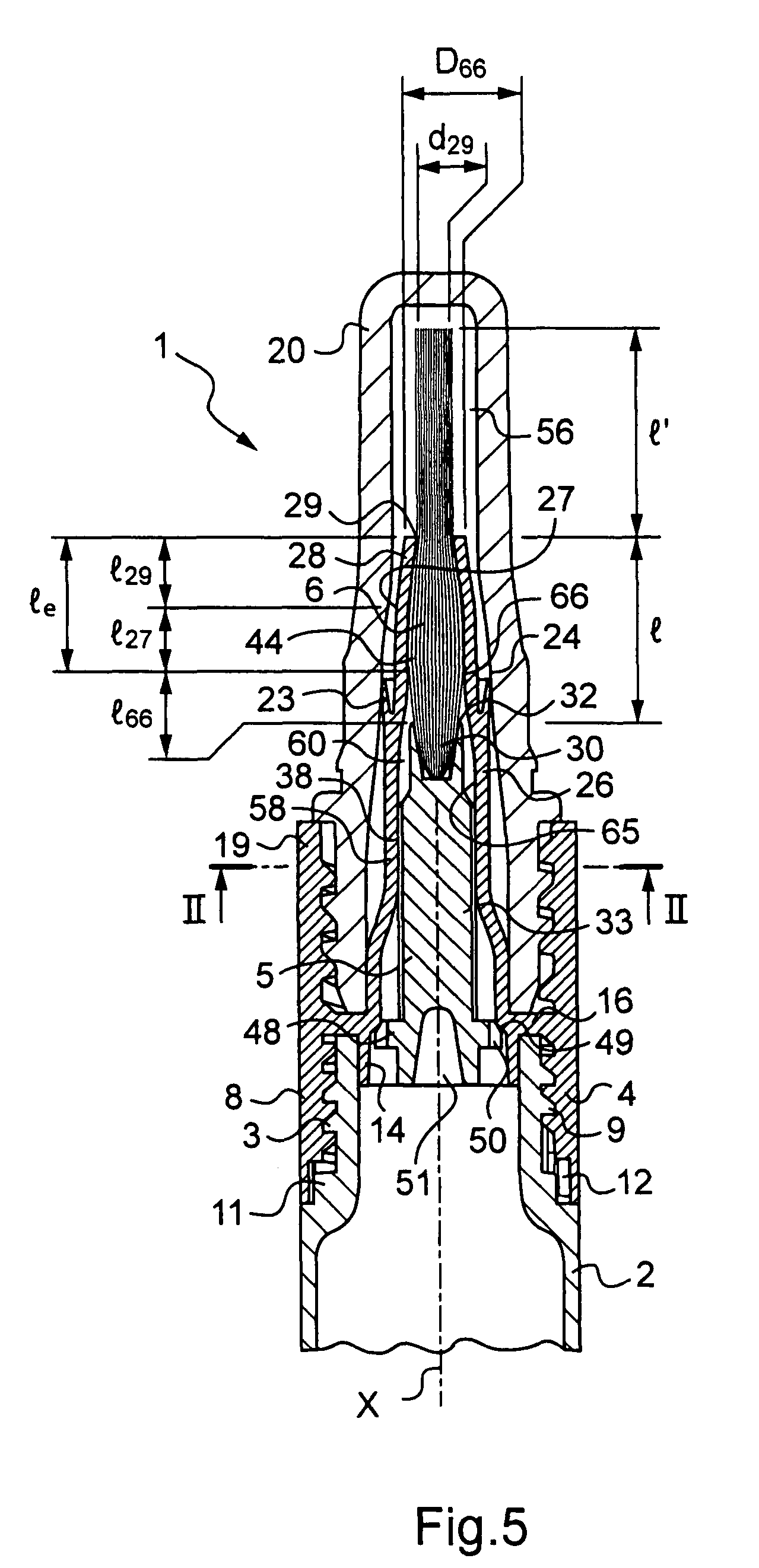
[0017]The invention thus makes it possible to create one or more channels of relatively small section between the applicator-element holder and the support, in such a manner as to create a relatively high head loss that is capable of slowing down the flow of composition even in the event of the pressure of the composition in the reservoir being relatively high.
[0018]In addition, by surrounding the applicator element, the support makes it possible to create an intermediate chamber into which the longitudinal channel(s) open out, improving the degree to which the bristles are impregnated by the composition.
[0019]The quality of the application and the comfort in use are thereby improved, and the invention enables the device to be adapted more easily to a composition presenting given Rheological characteristics, e.g. by selecting the size and the number of longitudinal channels, and the length over which the applicator element is covered by the tubular sheath of the support.
[0020]In an embodiment of the invention, the tubular sheath may thus extend around the applicator element over a length of at least 4 millimeters (mm), even of at least 6 mm, 8 mm, or 10 mm, thereby enabling the applicator element to be impregnated in satisfactory manner.
[0028]The flared cross-section of the housing may enable the bristles to move apart from one another more easily outside the housing.
[0029]The bristles may thus occupy more of the intermediate chamber, thereby improving their impregnation and slowing down the flow of composition.

Problems solved by technology

The bundle of bristles can thus turn out to be insufficiently impregnated in some circumstances.
In addition, there exists the risk of excess composition being delivered onto the applicator element, since once the composition has passed through the orifices of the applicator-element holder, it flows without being braked over the applicator element.

Method used


Image

  • Packaging and applicator device
  • Packaging and applicator device
  • Packaging and applicator device

Examples


Embodiment Construction

[0044]The packaging and applicator device 1 shown in FIG. 1 includes a reservoir 2 of longitudinal axis X containing at least one composition for application, provided with a neck 3 on which there is disposed a support 4 serving to fasten an applicator-element holder 5 on the reservoir 2.

[0045]In the embodiment under consideration, the bottom portion of the support 4 comprises a mounting skirt 8 that is internally threaded, and the neck 3 includes a corresponding external thread 9.

[0046]At its base, the neck 3 can be made with an anti-rotation ratchet 11, and the mounting skirt 8 can include an anti-rotation ratchet 12 making it possible to screw the mounting skirt 8 onto the reservoir 2, and preventing it from being unscrewed therefrom.

[0047]As can be seen in FIG. 1, the support 4 can also include a sealing lip 14 that is engaged in the neck 3 and that is connected to the mounting skirt 8 via a transverse wall 16 that comes to bear against the top end of the neck 3.

[0048]At its top...


PUM


Abstract

The present invention relates to a packaging and applicator device comprising: a reservoir containing at least one composition for application; an applicator element that is secured to the reservoir at least during application; an applicator-element holder; and a support for fastening the applicator-element holder on the reservoir, the support including a tubular sheath surrounding the applicator-element holder and the applicator element over at least a fraction of its length, the tubular sheath and the applicator-element holder presenting facing surfaces in contact; at least one hollow longitudinal channel being formed in one of the surfaces, so as to enable the composition coming from the reservoir to flow towards the applicator element.

Description

[0001]This non provisional application claims the benefit of French Application No. 06 50970 filed on Mar. 21, 2006 and U.S. Provisional Application No. 60 / 792,323 filed on Apr. 17, 2006.[0002]The present invention relates to packaging and applicator devices comprising: a reservoir containing at least one composition for application; and an applicator element that is secured to the reservoir at least during application.BACKGROUND OF THE INVENTION[0003]European patent application EP 1 557 111 discloses a device of that type in which the applicator element can be constituted by a tuft of bristles stapled in a housing of an applicator-element holder.[0004]The composition is brought to the outside of the applicator element through orifices of the applicator-element holder.[0005]By way of example, the composition can be dispensed by pressing on the wall of the reservoir, when said wall is flexible.[0006]The composition is dispensed at the base of the bristles in a zone in which said bris...

Claims


Application Information

Patent Timeline
Patent Type & Authority Patents(United States)
IPC IPC(8): A46B11/00
CPCA45D34/042A46B11/0013A46B17/04A46B11/0093A46B2200/1046
Inventor ALBISETTI, NICOLAS
Owner LOREAL SA
Learn More