
Particulate filtering apparatus for marine diesel engines and method of operation and regeneration of said apparatus

a technology of marine diesel engines and filtering equipment, which is applied in the direction of mechanical equipment, engines, machines/engines, etc., can solve the problems of significant environmental pollution, inability to use particulate filters of the type currently used in the automotive sector, and excessive particulate accumulation

Active Publication Date: 2018-08-28
ECOSPRAY TECH
View PDF13 Cites 0 Cited by
  • Summary
  • Abstract
  • Description
  • Claims
  • Application Information

AI Technical Summary

Benefits of technology

[0009]The present invention therefore aims to resolve these issues by providing a particulate filtering apparatus that can, in particular, be used with marine diesel engines, which, as has been said, use low quality fuel, allowing a dry filtration of exhaust gases that is more efficient than wet filtration currently used in the sector and, which does not cool the gases so as to make a heat recovery possible without the problems of fouling the boilers used. The treated gas can thus be purified with seawater scrubbers to remove the SOx without polluting the water used with the above-mentioned hazardous compounds.
[0010]Within this aim, the object of the present invention is to provide a particulate filtering apparatus for the dry filtering of the exhaust gases of marine diesel engines that is able to eliminate or at least reduce the particulate in the exhaust gases without generating high head losses so as not to adversely affect engine performance.
[0011]A further object of the present invention is to provide an extremely reliable particulate filtering apparatus for the dry filtering of the exhaust gases of marine diesel engines, so that the engine does not have to be stopped for maintenance interventions.
[0012]Not least, the object of the present invention is to provide a particulate filtering apparatus for the dry filtering of the exhaust gases of marine diesel engines of small dimensions, so as to allow easy installation on board the naval unit.
[0013]A further object of the present invention is to remove soot from the exhaust gases so that the efficiency of the energy recovery boiler located in the exhaust system of the engine remains high over time thus reducing fouling on the exchange surfaces.
[0014]A further object of the present invention is to provide a method for the operation and regeneration of a particulate filtering apparatus for the dry filtering of the exhaust gases of marine diesel engines that allows the drawbacks of the wet filtering systems known in the prior art to be overcome.

Problems solved by technology

However, it also entails significant problems in terms of environmental pollution due to the pollutant content (sulphur, ashes, heavy metals, etc.)
In the marine sector, namely for the large diesel engines with which ships are equipped, on the other hand, there is not currently any dry filtration of the particulate as the high content of impurities in the naphthas used makes the use of particulate filters of the type currently used in the automotive sector substantially impossible, as they would immediately clog due to the high presence of non-combustible particulate in the exhaust fumes.
In addition, these particulate filters, which generally use oxidising catalysts to improve oxidation of the organic fraction, and thus the combustion of soot, in the event of these being used in marine engines that burn diesel fuel containing sulphur, would result in oxidation of the SO2 to SO3, further increasing the particulate to an excessive extent.
The efficacy of the “scrubber” on the particulate matter is however somewhat limited and is also limited to transferring the particulate from the gaseous phase to the liquid phase polluting the seawater used therein.

Method used


Image

  • Particulate filtering apparatus for marine diesel engines and method of operation and regeneration of said apparatus

Examples


Embodiment Construction

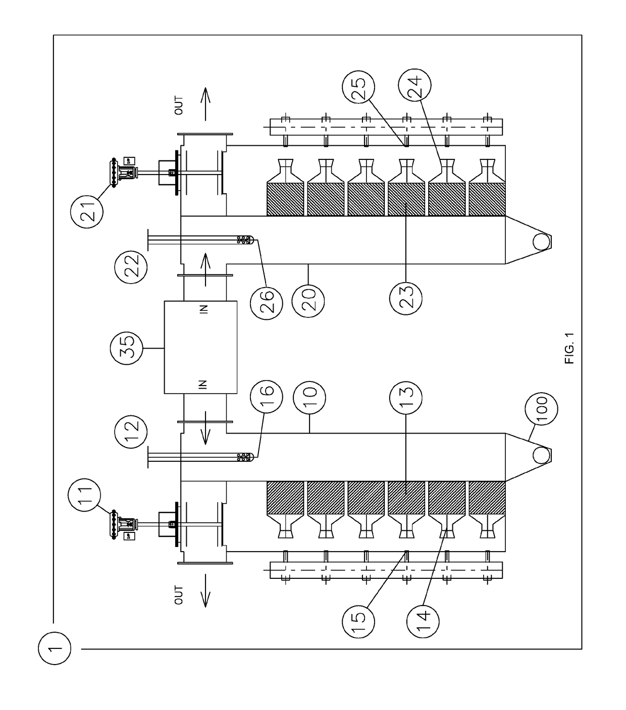
[0019]The particulate filtering apparatus 1 according to the present invention comprises a plurality of compartments 10, 20 arranged in parallel with respect to the flow of the exhaust gases. The flow of the exhaust gases entering the compartment 10 is schematically shown by the IN arrow in FIG. 1, which indicates the flow entering in the compartment 10 from the inlet conduit 35.

[0020]Each of said compartments 10, 20 is equipped with a shut-off valve, respectively indicated by the reference numbers 11 and 21 in the example of FIG. 1, adapted to adjust, and if necessary to stop, the gas flow through the relevant compartment. The flow lines in FIG. 1 represent the path of the gas passing through a compartment, in particular the compartment 10 the filter operation of which will be described below. The one or more other compartments will have an analogous structure, and what is shown herein with reference to the compartment 10 can also be taken as valid for the other compartments, for c...


PUM


Abstract

A particulate filtering apparatus for dry filtering exhaust gases of a diesel engine includes at least two compartments independently arranged in parallel with respect to a flow of the exhaust gases. Each of the compartments is equipped with at least one shut-off valve for regulating the flow of gas passing through the compartment and further includes one or more filters adapted to hold the particulate and an emission device to generate a countercurrent gas pulse flow at the one or more filters. A central control unit operates and controls the at least one shut-off valve and of said emission device. Each of the at least two compartments further includes an injector operably controlled by the central control unit for the inlet of hot gases into the at least two compartments.

Description

[0001]This application is a national stage application under 35 U.S.C. § 371 of PCT Application No. PCT / IB2013 / 054499, filed May 31, 2013, which claims the priority benefit of Italy Application No. MI2012A000952, filed Jun. 1, 2012.FIELD OF THE INVENTION[0002]The present invention relates to a particulate filtering apparatus for marine diesel engines and a method of operation and regeneration of said apparatus.BACKGROUND OF THE INVENTION[0003]As is known, large marine diesel engines use a heavy oil referred to as heavy fuel oil (HFO) as fuel. This oil is constituted by a mixture of paraffins and aliphatic hydrocarbons and with a high sulphur content (1%-3.5%)[0004]The use of this fuel is substantially imposed on large ships for economic reasons, in that being an unrefined fuel and being of a lower quality with respect to the fuel used in diesel engines for automotive use, it an be purchased at a markedly lower cost. However, it also entails significant problems in terms of environme...

Claims


Application Information

Patent Timeline
Patent Type & Authority Patents(United States)
IPC IPC(8): F01N3/02F01N3/023F01N3/032F01N13/00F01N3/30F01N3/022
CPCF01N3/0233F01N3/0222F01N3/0232F01N3/0234F01N3/032F01N13/011F01N3/306F01N2610/08F01N2330/06F01N2590/02F01N2590/08F01N2610/02Y02T10/12
Inventor ARCHETTI, MAURIZIO
Owner ECOSPRAY TECH
Learn More