Electrical female terminal

a technology of electric female terminals and terminals, which is applied in the direction of coupling contact members, coupling device connections, electrical apparatus, etc., can solve the problems of unable to sized for a 0.5 terminal system, and not providing a proper resilient normal force for tin terminals

Active Publication Date: 2011-05-31
J S T CORP
View PDF8 Cites 25 Cited by
  • Summary
  • Abstract
  • Description
  • Claims
  • Application Information

AI Technical Summary

Benefits of technology

[0009]It is an object of the present invention to provide an electrical female terminal that can be scaled-down in size while providing a proper resilient normal force.
[0010]It is another object of the invention to provide an electrical female terminal that can be scaled-down in size without compromising its structural integrity.
[0011]It is yet a further object of the invention to provide a scaled-down electrical female terminal that has an L-shaped spring assembly that can be manufactured without multiple, weakening corner cuts.

Problems solved by technology

A drawback of this female terminal is that it cannot be sized for a 0.5 terminal system.
Also, if the main blade terminal contacting portion is scaled-down, it will not provide a proper resilient normal force for tin terminals.
Like the above prior art female terminal, this female contact, if scaled-down, will not provide a proper resilient normal force for tin terminals.
Additionally, scaling-down of this female contact will compromise its structural integrity.
Unfortunately, to create the “L-shape” of this receptacle terminal, multiple corner cuts are required during its fabrication.
As a result, its structural integrity is weakened.
Furthermore, its structure is complex and difficult to manufacture.

Method used


Image

  • Electrical female terminal
  • Electrical female terminal
  • Electrical female terminal

Examples


Embodiment Construction

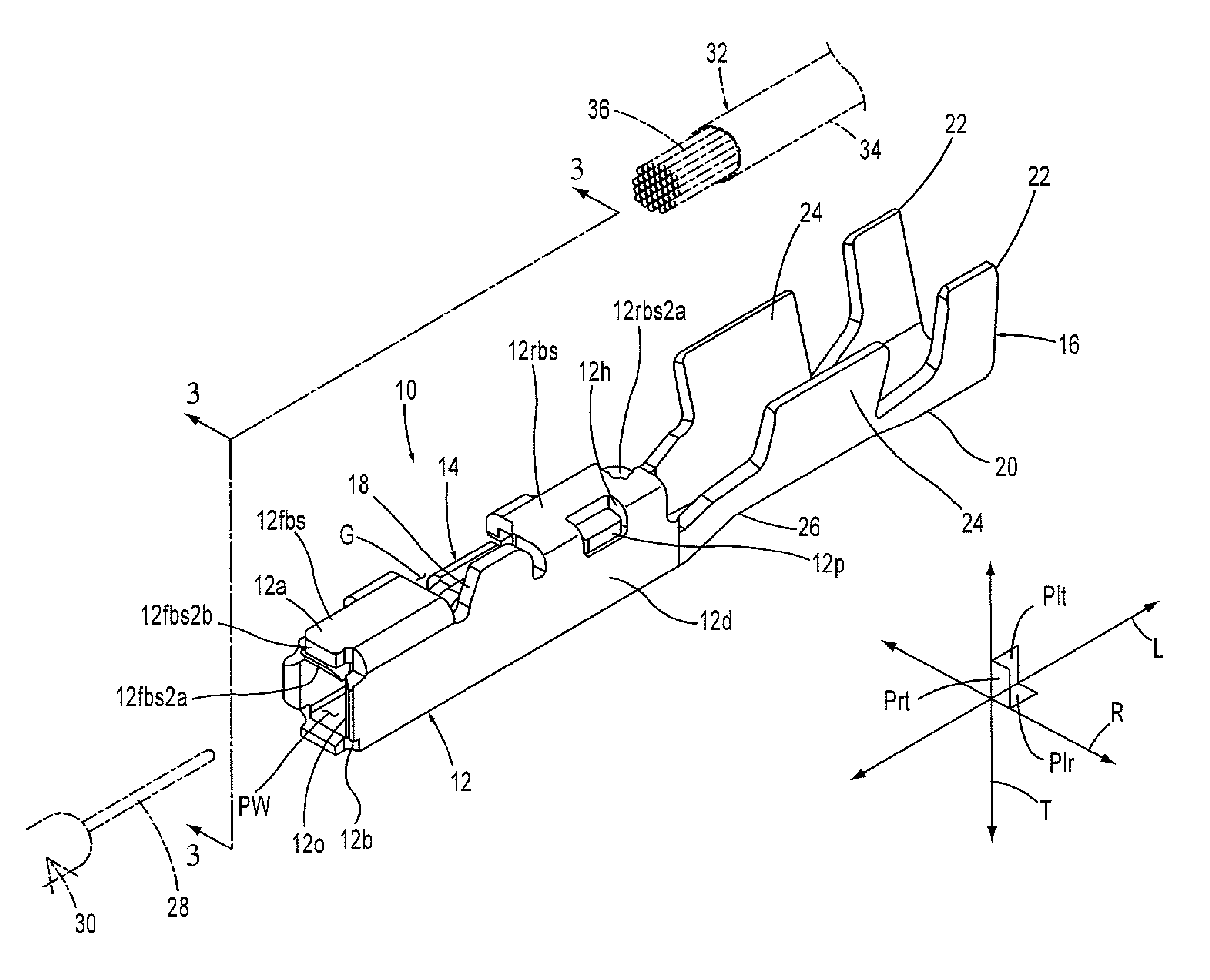
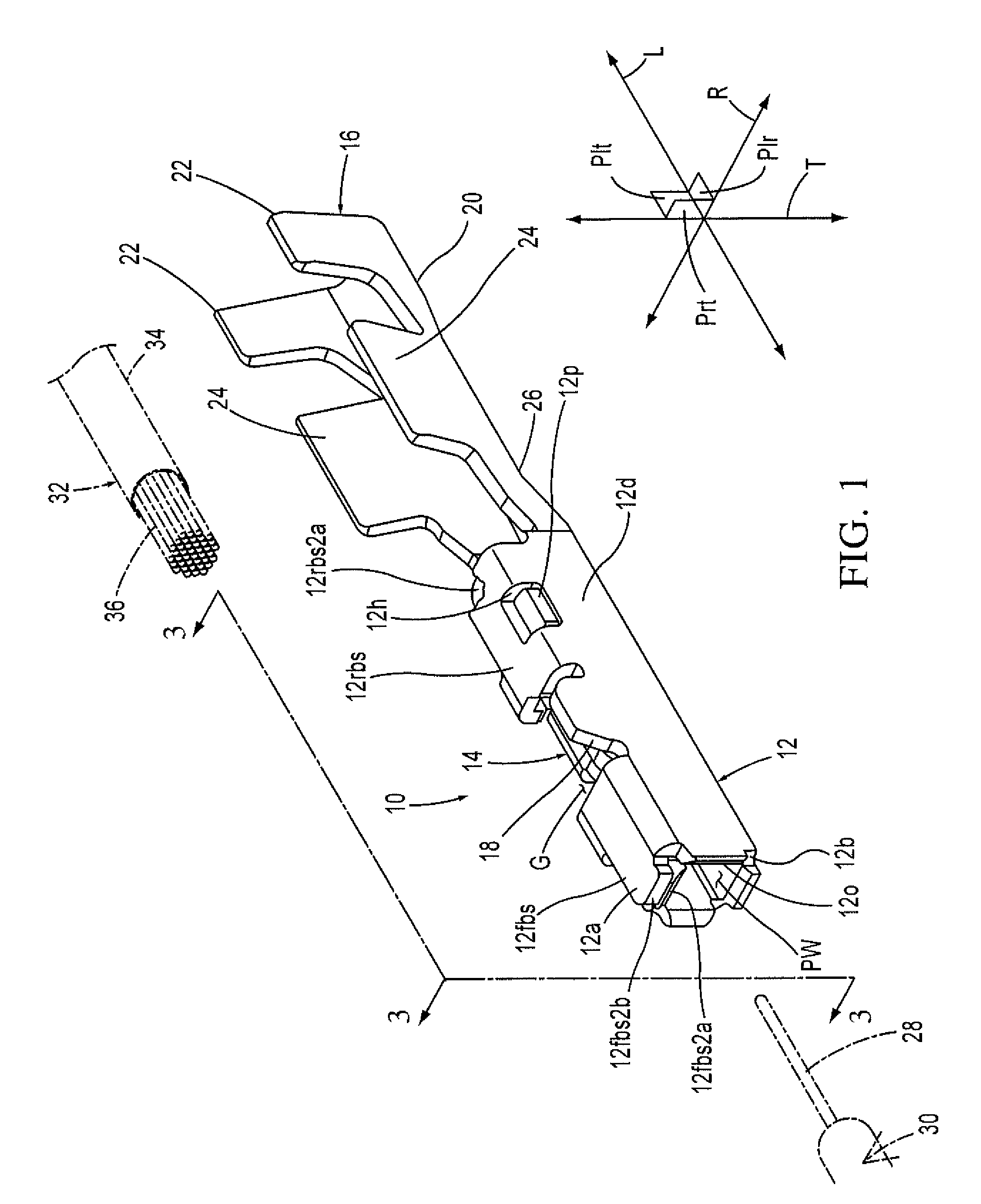
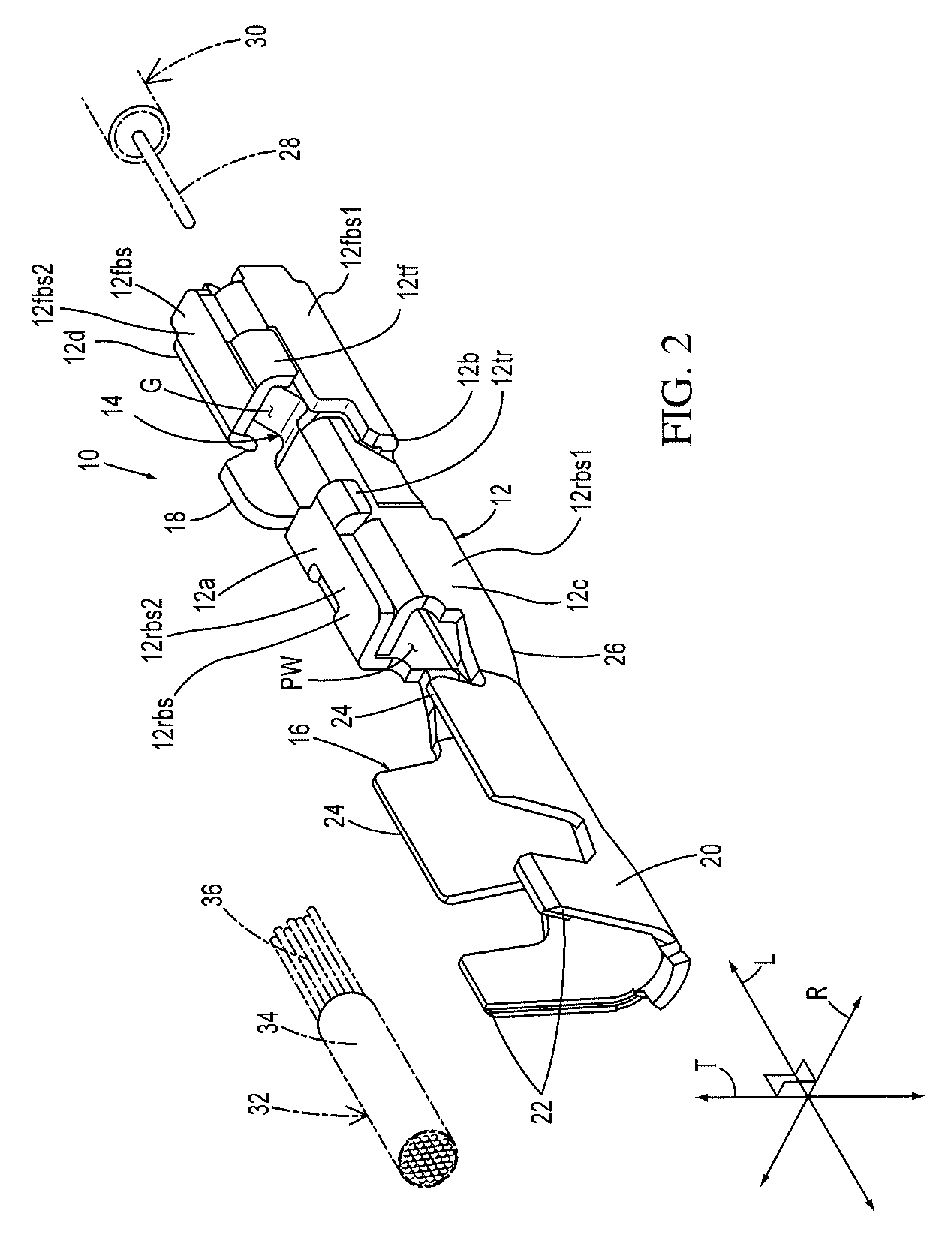
[0030]The detailed description of the exemplary embodiment of the present invention is hereinafter described. However, a skilled artisan will appreciate that terms such as “top”, “bottom”, “forwardly”, “rearwardly”, “upper”, “lower” and the like are used herein for the purpose of simplifying the explanation of the exemplary embodiment of the present invention and of ease of understanding of the exemplary embodiment of the present invention as illustrated on the sheets of drawing figures. These terms are intended to orient the exemplary embodiment of the present invention on the sheets of drawing figures only for ease of understanding the invention and are not intended to orient the exemplary embodiment of the present invention in three-dimensional space. Thus, these terms should not be construed in any manner to narrow scope of the invention. One of ordinary skill in the art would easily comprehend that non-descriptive, non-orienting terms such as “first” and “second” and the like c...


PUM


Abstract

An electrical female terminal includes a female terminal body and a spring assembly. The female terminal body extends along and about a longitudinal axis and has a top wall, an opposite bottom wall and a pair of opposing side walls that connected to each other to form a generally box-shaped passageway extending through the female terminal body. The spring assembly has a beam portion, an interconnect portion and a contact portion. The beam portion is connected to one of the side walls. The interconnect portion is connected generally perpendicularly to the beam portion and interconnects the beam portion and the contact portion. The contact portion is connected to the interconnect portion and projects forwardly from the interconnect portion in a cantilevered manner. When a male terminal pin is inserted into the electrical female terminal, the spring assembly twists towards the one side wall to which the beam portion is connected.

Description

FIELD OF THE INVENTION[0001]The present invention is related to an electrical female terminal. More specifically, the present invention is directed to an electrical female terminal that includes a spring assembly that twists when an electrical male terminal is inserted into the electrical female terminal.BACKGROUND OF THE INVENTION[0002]Many types of electrical female terminals are known in the art. One such electrical female terminal is described in U.S. Pat. No. 3,713,080. This female terminal receives a blade terminal. The main elements forming the female terminal are first, second, third and fourth walls which are joined together into an integral unit at their edges between the first and the second, the second and the third, and the third and the fourth walls. A co-operable lock device is formed, in part, on a free end of the first wall and, in part, on a free end of the fourth wall. The co-operable lock device locks the walls into a closed configuration to define therein an int...

Claims


Application Information

Patent Timeline
Patent Type & Authority Patents(United States)
IPC IPC(8): H01R13/11
CPCH01R13/111
Inventor CHEN, PINGHASEGAWA, ROBERT
Owner J S T CORP
Why Eureka
Try Eureka