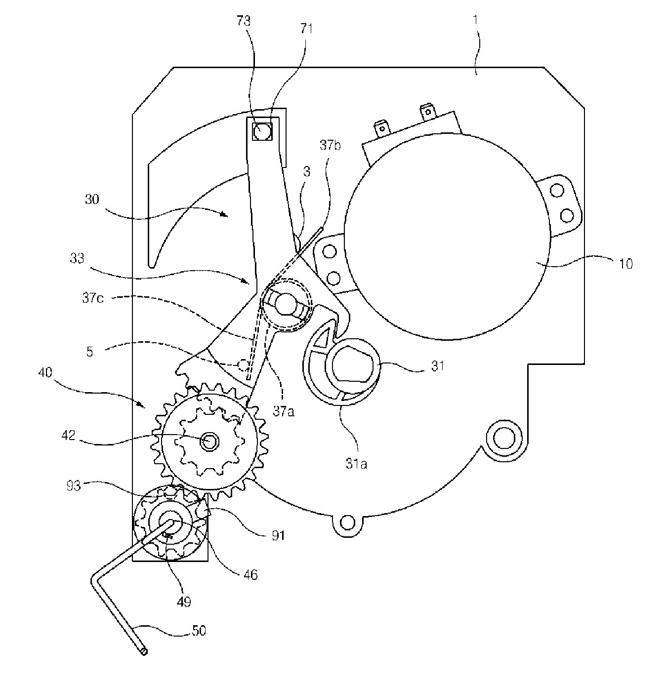
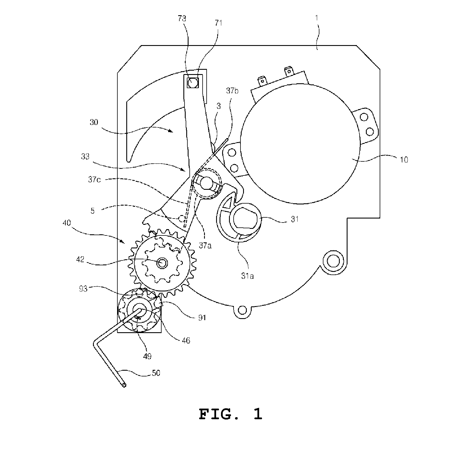
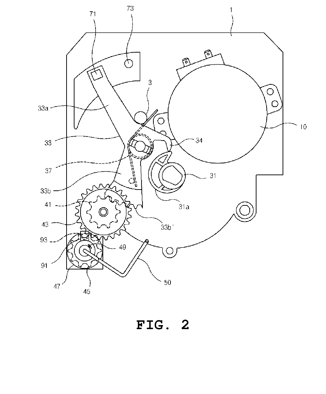
Apparatus and method for driving icemaker of refrigerator

a technology of icemaker and ice maker, which is applied in the direction of ice production, lighting and heating apparatus, domestic applications, etc., can solve the problems of inability to provide precise rotation force, adverse influences on and inability to so as to increase the durability of the components and accurately sense the ice-full state. , the effect of precise rotation for

Active Publication Date: 2015-03-26
SCD CO LTD
View PDF22 Cites 11 Cited by
  • Summary
  • Abstract
  • Description
  • Claims
  • Application Information

AI Technical Summary

Benefits of technology

[0047]According to the embodiments of the present invention, advantages are provided in that, since interference between an ejector and the ice cubes present in an icemaker is prevented when sensing an ice-full state, it is possible to accurately sense the ice-full state.
[0048]Also, according to the embodiments of the present invention, advantages are provided in that, since a first torsion spring is mounted to an intermediate gear with a small rotation angle ratio, only a minimum amount of torque is transferred to other components such as an ice-detecting lever, whereby the durability of the components may be increased and a precise rotation force may be provided.
[0049]Further, according to the embodiments of the present invention, advantages are provided in that, since the axial center of rotation of a second torsion spring biasing the ice-detecting lever to elastically contact the cam surface of a cam gear is defined at a position that faces the other end (the revolving end) of the ice-detecting lever, a minimum moment is substantially constantly applied, whereby the durability of components may be increased and a precise rotation force may be provided.

Problems solved by technology

As a consequence, problems may be caused in that adverse influences are likely to be exerted on the components interlocked with the ice-detecting lever 33, for example, the durability of the components is likely to deteriorate or a precise rotation force is not likely to be provided.

Method used


Image

  • Apparatus and method for driving icemaker of refrigerator
  • Apparatus and method for driving icemaker of refrigerator
  • Apparatus and method for driving icemaker of refrigerator

Examples


Embodiment Construction

[0061]The objects, advantages and novel features of the invention will become more apparent from the following detailed description of exemplary embodiments when taken in conjunction with the accompanying drawings. In the following description, when adding reference numerals to the component elements of respective drawings, the same component elements will be designated by the same reference numerals although they are shown in different drawings. The terms such as “first”, “second”, “one portion”, “the other portion”, and so forth are to distinguish certain component elements from other component elements, and thus, the component elements are not limited by such terms. When it is considered that a specific description for the related known technology unnecessarily obscures the purpose of the invention, the detailed descriptions thereof will be omitted.

[0062]Hereafter, exemplary embodiments of the present invention will be described in detail with reference to the accompanying drawin...


PUM


Abstract

An apparatus and a method for driving an icemaker for making ice cubes in a refrigerator. An ice-full state is sensed in such a way as to rotate an ejector and a cam gear in a reverse direction (opposite to an ice-ejecting direction), thereby preventing interference with the ice cubes present in the icemaker and thus enabling the ice-full state to be accurately sensed. A first torsion spring is mounted to an intermediate gear with a small rotation angle ratio to allow only a minimum amount of torque to be transferred to other components such as an ice-detecting lever, thereby increasing the durability of the components and providing a precise rotation force. The axial center of rotation of a second torsion spring is defined at a position that faces the other end (the revolving end) of the ice-detecting lever, to allow a minimum moment to be substantially constantly applied.

Description

TECHNICAL FIELD[0001]The present invention relates to an apparatus and a method for driving an icemaker for making ice cubes in a refrigerator or the like, and more particularly, the present invention relates to an apparatus and a method for driving an icemaker for making ice cubes in a refrigerator or the like, in which an ice-full state is sensed in such a way as to rotate an ejector and a cam gear in a reverse direction (opposite to an ice-ejecting direction), thereby preventing interference with the ice cubes present in the icemaker and thus enabling the ice-full state to be accurately sensed.[0002]Also, the present invention relates to an apparatus and a method for driving an icemaker for making ice cubes in a refrigerator or the like, in which a first torsion spring is mounted to an intermediate gear with a small rotation angle ratio to allow only a minimum amount of torque to be transferred to other components such as an ice-detecting lever, thereby increasing the durability ...

Claims


Application Information

Patent Timeline
Patent Type & Authority Applications(United States)
IPC IPC(8): F25C5/16
CPCF25C5/16F25C1/04F25C2400/10F25C2700/02F25C5/00F25C2305/024
Inventor PARK, JIN SUNG
Owner SCD CO LTD
Why Eureka
Try Eureka