Filter cleaning system for a vacuum cleaner

Inactive Publication Date: 2011-05-31
AB ELECTROLUX
View PDF23 Cites 10 Cited by
  • Summary
  • Abstract
  • Description
  • Claims
  • Application Information

AI Technical Summary

Benefits of technology

[0007]A first purpose of this invention is to create an arrangement that eliminates the above drawbacks making it possible for the operator to change a filter quickly and to easily keep track of the filter condition. Another purpose of the invention is to create an arrangement that makes it possible to easily clean the filter without taking the vacuum cleaner out of operation or using cumbersome methods for cleaning the filter.

Problems solved by technology

It is a disadvantage that the operator of all of the vacuum cleaners mentioned above has to remove the filter and replace it or clean it since replacement means that the consumer always has to keep an eye on the consumption of the filter and to buy new filters when necessary whereas cleaning means that the vacuum cleaner can not be used during the washing period and moreover demands for certain cumbersome activities from the operators side.
A clear disadvantage with the first arrangement is the need for two motors whereas there is no indication how to clean the auxiliary filter in the second arrangement.

Method used


Image

  • Filter cleaning system for a vacuum cleaner
  • Filter cleaning system for a vacuum cleaner
  • Filter cleaning system for a vacuum cleaner

Examples


Embodiment Construction

[0019]The following description is intended to convey a thorough understanding of the invention by providing a number of specific embodiments and details involving a vacuum cleaner. It is understood, however, that the invention is not limited to these specific embodiments and details, which are exemplary only. It is further understood that one possessing ordinary skill in the art, in light of known systems and methods, would appreciate the use of the invention for its intended purposes and benefits in any number of alternative embodiments.

[0020]Embodiments of the invention described herein comprise a canister vacuum. However, the invention is not limited to a canister vacuum, but rather, a person having ordinary skill in the art would recognize that the invention can also be applied to upright vacuums or other apparatus requiring particle separation from an airflow.

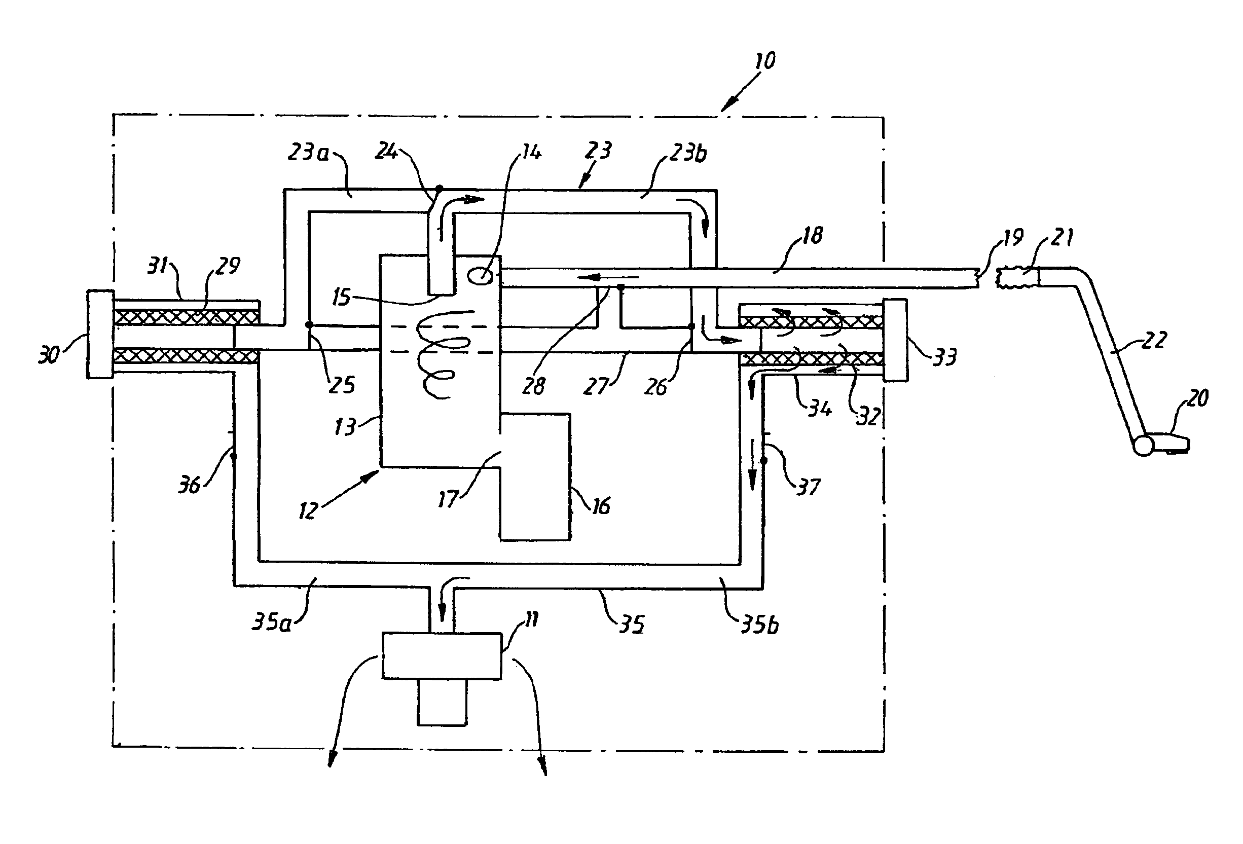
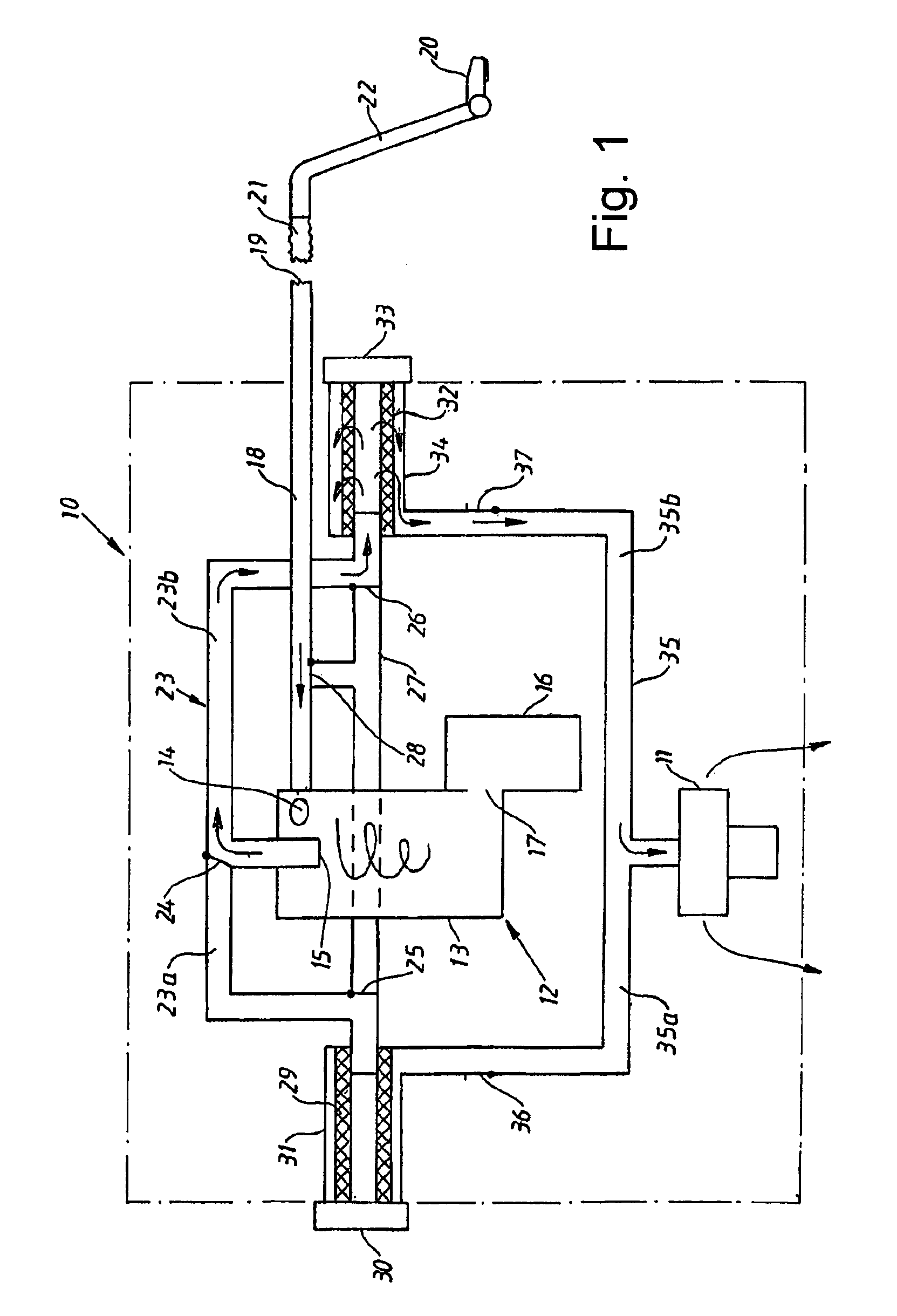
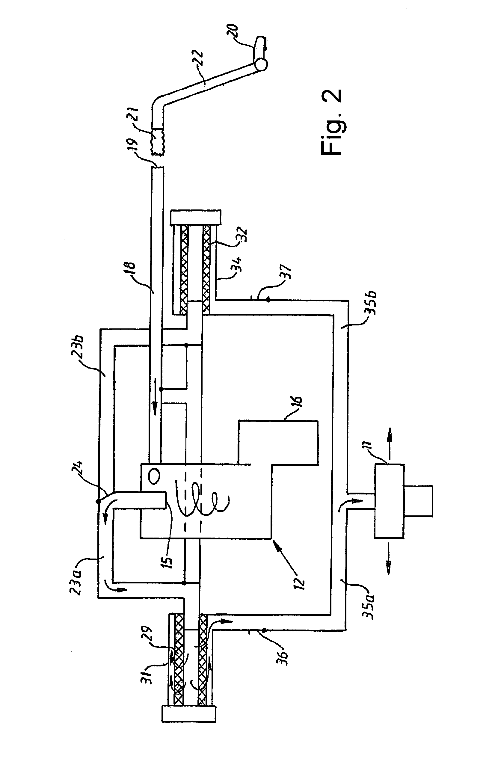
[0021]Three embodiments of the invention will now be described by reference to the accompanying schematic drawings on w...


PUM

PropertyMeasurementUnit
Flow rateaaaaaaaaaa
Lengthaaaaaaaaaa
Distanceaaaaaaaaaa

Abstract

This invention relates to a vacuum cleaner comprising a body with a vacuum source. The vacuum cleaner is provided with at least two filter chambers, a first filter chamber for a first filter means in a surface cleaning mode and a second chamber for the same or a second filter means in a filter cleaning mode.

Description

FIELD OF THE INVENTION[0001]The present invention relates to a vacuum cleaner. More particularly, embodiments of the invention relate to apparatus and methods for cleaning filters used in a vacuum cleaner.BACKGROUND OF THE INVENTION[0002]Traditional vacuum cleaners usually belong to two different categories called canister cleaners and upright cleaners. The canister vacuum cleaner comprises a housing enclosing an electric fan unit that creates an airflow from a vacuum cleaner nozzle through a tube shaft and a hose and further through a separating system comprising a porous bag collecting the dust before the air reaches the fan and leaves the housing to the ambient air. The upright vacuum cleaner differs from the canister cleaner in that the tube shaft and the hose are eliminated and that the nozzle, that often is provided with a rotating brush, is pivotally connected to the vacuum cleaner housing. The housing encloses the fan unit and the air pervious dust bag and is provided with a...

Claims


Application Information

Patent Timeline
IPC IPC(8): B01D39/00A47L9/16A47L9/20
CPCA47L9/20A47L9/1666Y10S55/03A47L9/16
Inventor MENRIK, LINDAGRAY, ANNA-KARINLOFNES, FINNMIEFALK, HAKANJANSSON, MATTIASTRYDEGARD, ANNA-KARINBELIN, MATHIASHOLM, HENRIKMENNBORG, LARS
Owner AB ELECTROLUX
Why Eureka
Try Eureka