Arc-resistant switchgear enclosure with ambient air ventilation system

a technology of ambient air and switchgear enclosure, which is applied in the direction of substation/switching arrangement details, cooling/ventilation/heating modification, electrical apparatus casing/cabinet/drawer, etc., and can solve problems such as arcing faults, arcing faults, and other hazardous conditions of switchgear enclosures

Active Publication Date: 2011-05-31
SCHNEIDER ELECTRIC USA INC
View PDF22 Cites 83 Cited by
  • Summary
  • Abstract
  • Description
  • Claims
  • Application Information

AI Technical Summary

Problems solved by technology

In addition to current overloads, switchgear enclosures may encounter other hazardous conditions known as arcing faults.
Arcing faults occur when electric current “arcs,” flowing through ionized gas between conductors, such as between two ends of broken or damaged conductors, or between a conductor and ground in a switchgear enclosure.
Arcing faults typically result from corroded, worn or aged wiring or insulation, loose connections and electrical stress caused by repeated overloading, lightning strikes, etc.
Particularly in medium- to high-voltage power distribution systems, the ionized gases associated with arcing faults may be released at pressures and temperatures sufficient to damage the switchgear equipment and cause deadly harm to anyone in close proximity.
Meeting the temperature limits in arc-resistant switchgear enclosures becomes more difficult as the current rating of the switchgear increases, and it becomes necessary to use air ventilation systems to maintain the required temperatures.
These closure mechanisms can add to the cost of switchgear enclosures, and can also introduce reliability issues in preventing an arc exhaust.

Method used


Image

  • Arc-resistant switchgear enclosure with ambient air ventilation system
  • Arc-resistant switchgear enclosure with ambient air ventilation system
  • Arc-resistant switchgear enclosure with ambient air ventilation system

Examples


Embodiment Construction

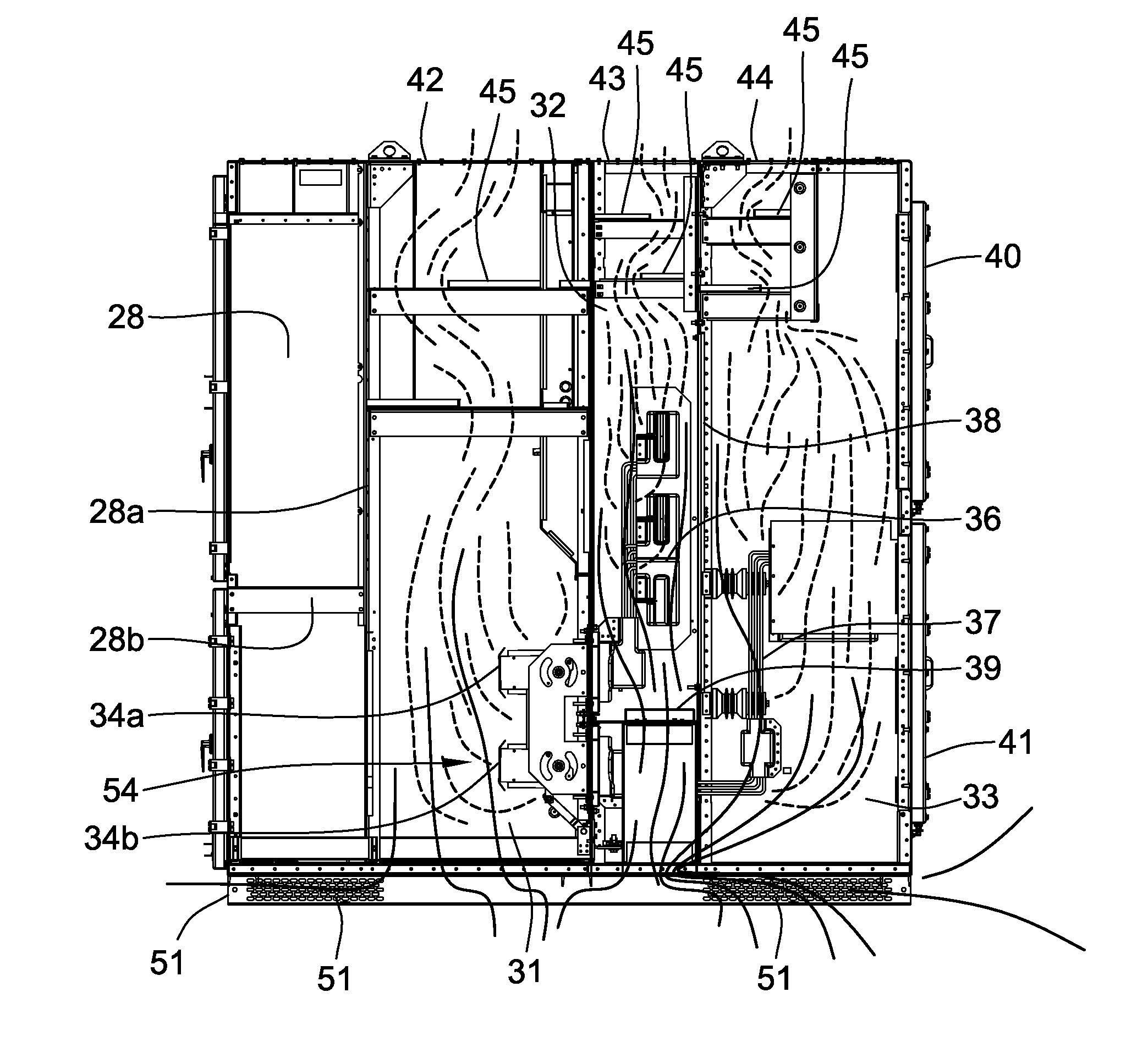
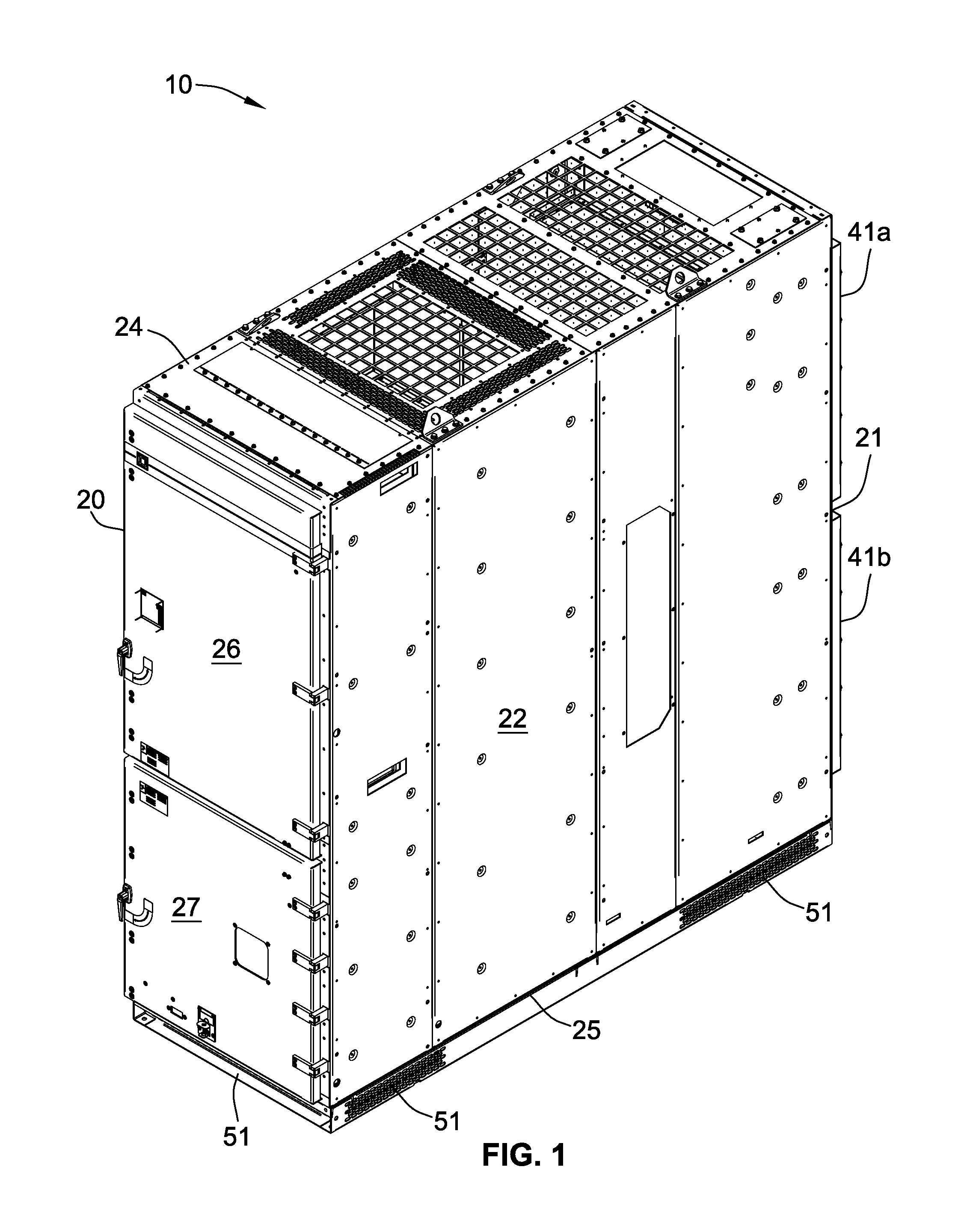
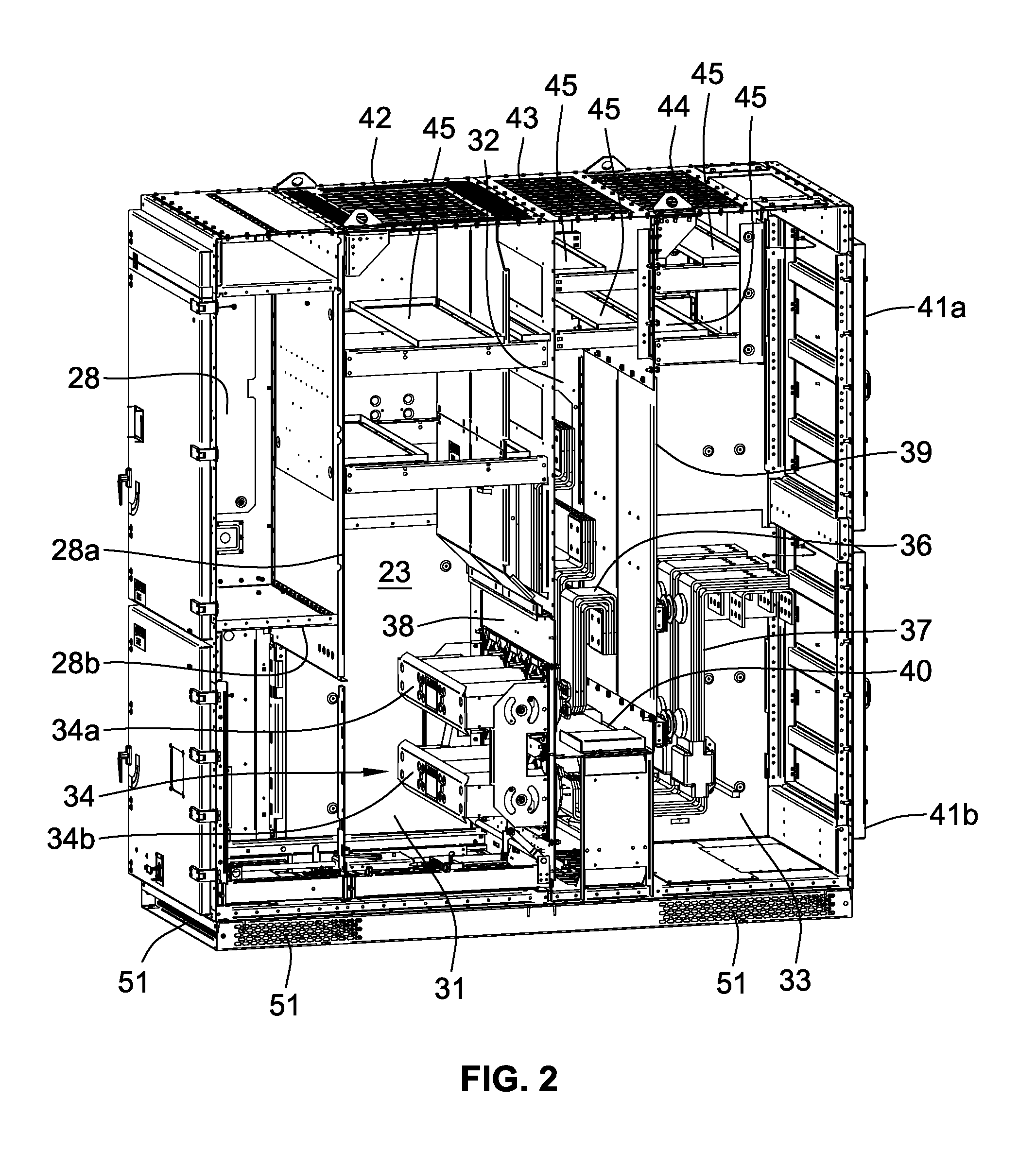
[0020]Turning now to the drawings and referring first to FIGS. 1 and 2, there is shown a switchgear enclosure 10 that includes vertical front and back walls 20 and 21, a pair of vertical side walls 22 and 23 joined to the front and back walls, and top and bottom walls 24 and 25 joined to all the vertical walls 20-23. Mounted on the front wall 20 are upper and lower hinged doors 26 and 27, and the upper door 26 opens into a low-voltage compartment 28 that is isolated from the rest of the interior of the enclosure 10 by partitions 28a and 28b (see FIG. 2). The lower door 27 opens into a circuit breaker compartment 31, which is the first of three higher-voltage compartments 31, 32 and 33. Compartment 32 is a main bus compartment, and compartment 33 is a cable compartment.

[0021]In the breaker compartment 31, a circuit breaker (not shown) is plugged into a circuit breaker stab assembly 34 that includes a pair of circuit breaker sockets 34a and 34b which are connected to line-side bus bar...


PUM


Abstract

An arc-resistant enclosure for electrical switchgear which includes solid front and back walls, a pair of solid side walls joined to the front and back walls, a ventilated roof joined to the side walls and the front and back walls, and a ventilated base joined to the side walls and the front and back walls. Internal partitions divide the space enclosed by the front, back, side, top and bottom walls into multiple compartments for housing different types of components. The ventilated base forms air-intake ports for admitting ambient air into a plurality of the compartments, and the ventilated roof forms air-exhaust ports for allowing air to be exhausted from the compartments. As air inside the enclosure is heated by the switchgear, the hot air rises through the switchgear compartments and is exhausted through the top air-exhaust ports, and replacement ambient air is drawn into the bottoms of the compartments through the air-intake ports.

Description

FIELD OF THE INVENTION[0001]The present invention relates generally to electrical switchgear enclosures and, more particularly, to arc-resistant electrical switchgear enclosures having ambient air ventilation systems.BACKGROUND OF THE INVENTION[0002]Switchgear enclosures are commonly employed in electrical power distribution systems for enclosing circuit breakers and other switching equipment associated with the distribution system. Typically, switchgear enclosures are comprised of a number of individual stacked or adjacent compartments, and receive electrical power from a power source and distribute is the electrical power through one or more feeder circuits to one or more loads. Switchgear enclosures typically include circuit protection device for interrupting electric power in a particular feeder circuit in response to hazardous current overloads in the circuit. A circuit protection device in electrical equipment can be a circuit breaker, fuse and switch combination, contactor an...

Claims


Application Information

Patent Timeline
Patent Type & Authority Patents(United States)
IPC IPC(8): H05K7/20
CPCH02B13/025H02B1/56
Inventor MOTLEY, GREGORY O.WAYNICK, DALEBYRON, ELDRIDGE R.DE LA CRUZ, ABRAHAM
Owner SCHNEIDER ELECTRIC USA INC
Why Eureka
Try Eureka