Loudspeaker apparatus

a loudspeaker and loudspeaker technology, applied in the direction of deaf-aid sets, transducer details, electrical transducers, etc., can solve the problems of difficult to achieve sufficient low-frequency sound reproduction, difficult for the loudspeaker apparatus, and difficult for the large-size loudspeaker unit, etc., to achieve the effect of expanding the low-frequency reproduction band

Active Publication Date: 2011-05-31
PANASONIC CORP
View PDF3 Cites 40 Cited by
  • Summary
  • Abstract
  • Description
  • Claims
  • Application Information

AI Technical Summary

Benefits of technology

[0021]Therefore, an object of the present invention is to provide a loudspeaker apparatus capable of further expanding a low-frequency reproduction band.
[0022]A first aspect of the present invention is directed to a loudspeaker apparatus comprising a housing, an adsorptive material provided inside the housing, for physically adsorbing gas inside the housing, a vibration section including a diaphragm and provided in an opening formed in the housing, a drive section for driving the diaphragm to generate sound from the diaphragm, and a negative stiffness generating mechanism provided inside the housing, for reducing an acoustic stiffness inside the housing, the acoustic stiffness acting on the diaphragm.

Problems solved by technology

Therefore, loudspeaker apparatuses carried in the small-size or portable players have small-volume cabinets, so that an acoustic stiffness exhibited by the cabinet is large, and therefore, it is difficult to achieve low-frequency sound reproduction to a sufficient extent.
Therefore, it is difficult for the loudspeaker apparatus having a small cabinet internal volume V to reproduce a low-frequency sound region.
It is difficult for the large-size loudspeaker unit 102 to be incorporated into a small-size loudspeaker apparatus.
Here, if the amplitude of the cone-shaped diaphragm 105 exceeds the linear range, distortion of reproduced sound is increased, resulting in a reduction in reproduced sound quality.
However, the volumes of the magnets increase, leading to an increase in cost and an increase in weight of the vibration system.
As a result, the efficiency of the loudspeaker apparatus decreases.
For the above-described reasons, in the conventional loudspeaker apparatus of FIG. 16, there is a limitation on further expansion of the low-frequency sound reproduction band in a small-size loudspeaker apparatus, and it is difficult to achieve this.

Method used


Image

  • Loudspeaker apparatus
  • Loudspeaker apparatus
  • Loudspeaker apparatus

Examples


first embodiment

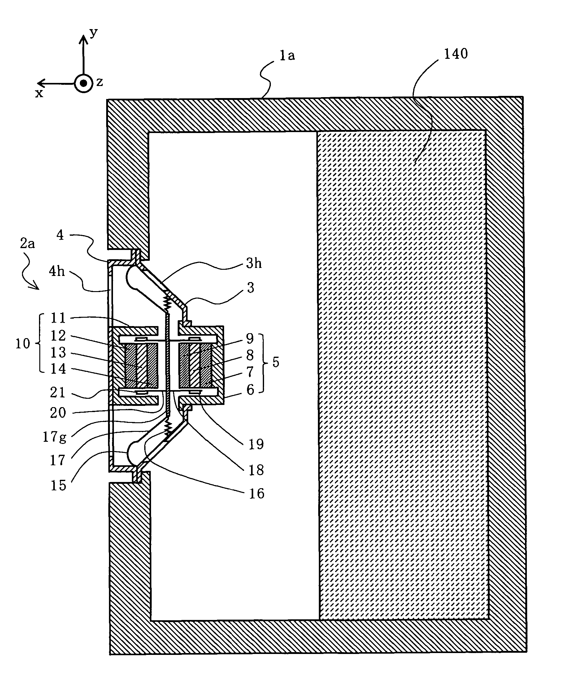
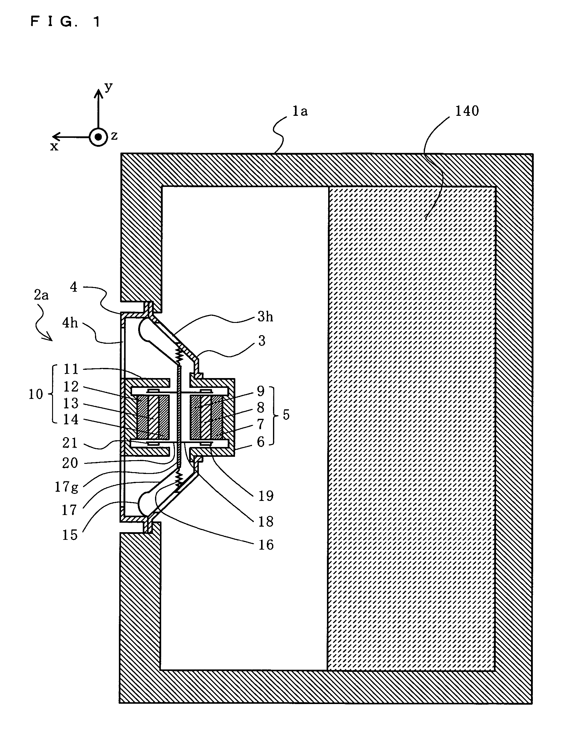
[0077]A loudspeaker apparatus according to a first embodiment of the present invention will be described with reference to FIG. 1. FIG. 1 is a cross-sectional view of a structure of the loudspeaker apparatus of the first embodiment. In FIG. 1, the loudspeaker apparatus roughly comprises a cabinet 1a, a loudspeaker unit 2a, and an adsorptive material 140. Note that the loudspeaker apparatus of this embodiment is, for example, of the closed-box type.

[0078]In FIG. 1, the adsorptive material 140 is provided inside the cabinet 1a. The adsorptive material 140 is a porous material which physically adsorbs gas (e.g., activated charcoal). Examples of activated charcoal include granular activated charcoal, fibrous activated charcoal, and the like. The porous material can adsorb gas with pores having a size of the order of micrometers. Other examples of the porous material include zeolite, silica (SiO2), alumina (Al2O3), zirconia (ZrO3), magnesia (MgO), triion tetroxide (Fe3O4), molecular siev...

second embodiment

[0116]A loudspeaker apparatus according to a second embodiment of the present invention will be described with reference to FIG. 3. The loudspeaker apparatus of this embodiment is different from that of the first embodiment in that a laser displacement gauge and a control circuit are newly provided. Hereinafter, a difference point will be mainly described. Note that FIG. 3 is a cross-sectional view of a structure of the loudspeaker apparatus of the second embodiment. FIG. 4 is a circuit block diagram of the loudspeaker apparatus of the second embodiment. In FIG. 3, the loudspeaker apparatus of this embodiment roughly comprises a cabinet 1a, a loudspeaker unit 2a, a laser displacement gauge 22, and a control circuit 23. Note that, since the loudspeaker unit 2a is similar to that of the first embodiment, is referenced with the same reference numeral as that of the first embodiment, and will not be described in detail.

[0117]In FIG. 4, the laser displacement gauge 22 detects a displacem...

third embodiment

[0122]A loudspeaker apparatus according to a third embodiment of the present invention will be described with respect to FIGS. 5 and 6. In the loudspeaker apparatus of this embodiment, a negative stiffness generating mechanism is provided separately from a loudspeaker unit. FIG. 5 is a cross-sectional view of a structure of the loudspeaker apparatus of the third embodiment. FIG. 6 is a cross-sectional view of the loudspeaker apparatus, taken along dash-dot-dot line A-B of FIG. 5, as viewed from the positive direction of the x axis.

[0123]In FIG. 5, the loudspeaker apparatus of this embodiment roughly comprises a cabinet 1b, a loudspeaker unit 2b, an adsorptive material 140, a port 25, and a negative stiffness generating mechanism 38. The loudspeaker unit 2b is attached to an opening formed in a front surface (the positive direction of the x axis) of the cabinet 1b. The loudspeaker unit 2b is, for example, a typical electrokinetic loudspeaker. The cabinet 1b is a housing which gives a...


PUM


Abstract

A loudspeaker apparatus comprises a housing, an adsorptive material provided inside the housing, for physically adsorbing gas inside the housing, a vibration section including a diaphragm and provided in an opening formed in the housing, a drive section for driving the diaphragm to generate sound from the diaphragm, and a negative stiffness generating mechanism provided inside the housing, for reducing an acoustic stiffness inside the housing, the acoustic stiffness acting on the diaphragm.

Description

BACKGROUND OF THE INVENTION[0001]1. Field of the Invention[0002]The present invention relates to a loudspeaker apparatus and, more particularly, to a loudspeaker apparatus which achieves low-frequency sound reproduction using a small-size cabinet.[0003]2. Description of the Background Art[0004]Conventionally, audio apparatuses are becoming more digitalized, and players for reproducing music sources are becoming smaller and more portable. However, loudspeaker apparatus for eventually reproducing sounds require large cabinets so as to sufficiently reproduce sounds in a low frequency region included in music sources. Therefore, loudspeaker apparatuses carried in the small-size or portable players have small-volume cabinets, so that an acoustic stiffness exhibited by the cabinet is large, and therefore, it is difficult to achieve low-frequency sound reproduction to a sufficient extent.[0005]Therefore, a loudspeaker apparatus has been disclosed in which a limit of low-frequency sound rep...

Claims


Application Information

Patent Timeline
Patent Type & Authority Patents(United States)
IPC IPC(8): H04R1/02H04R1/20H04R25/00H04R9/06H04R1/00H04R11/02
CPCH04R1/2803H04R2209/041
Inventor MATSUMURA, TOSHIYUKISAIKI, SHUJI
Owner PANASONIC CORP
Why Eureka
Try Eureka