Fluid friction clutch

a technology of friction clutches and friction plates, applied in the direction of clutches, fluid couplings, couplings, etc., can solve the problems of reducing the effectiveness of the pump, reducing slippage, and comparatively large degrees, and achieve the effect of stable clutch engagement degr

Active Publication Date: 2011-06-07
BORGWARNER INC
View PDF7 Cites 11 Cited by
  • Summary
  • Abstract
  • Description
  • Claims
  • Application Information

AI Technical Summary

Benefits of technology

This invention relates to a hydraulic braking system for vehicles. It includes a main chambers where oil flows during operation. There are also two smaller chambers called reservoirs that hold excess oil. These oils help keep everything running smoothly. In addition, there is a device called a scrapping element that helps move the oil around within the system. By doing this, the system can maintain consistent levels of pressure even if certain parts rotate quickly or slow down. Overall, this design ensures reliable performance and stability regardless of external factors like temperature changes or wear over time.

Problems solved by technology

The technical problem addressed in this patent is how to maintain a steady rotational speed of the secondary side (the output) when starting up or running downhill, even if the oil level in the working chamber fluctuates due to temperature variations or wear over time.

Method used


Image

  • Fluid friction clutch
  • Fluid friction clutch
  • Fluid friction clutch

Examples


Embodiment Construction

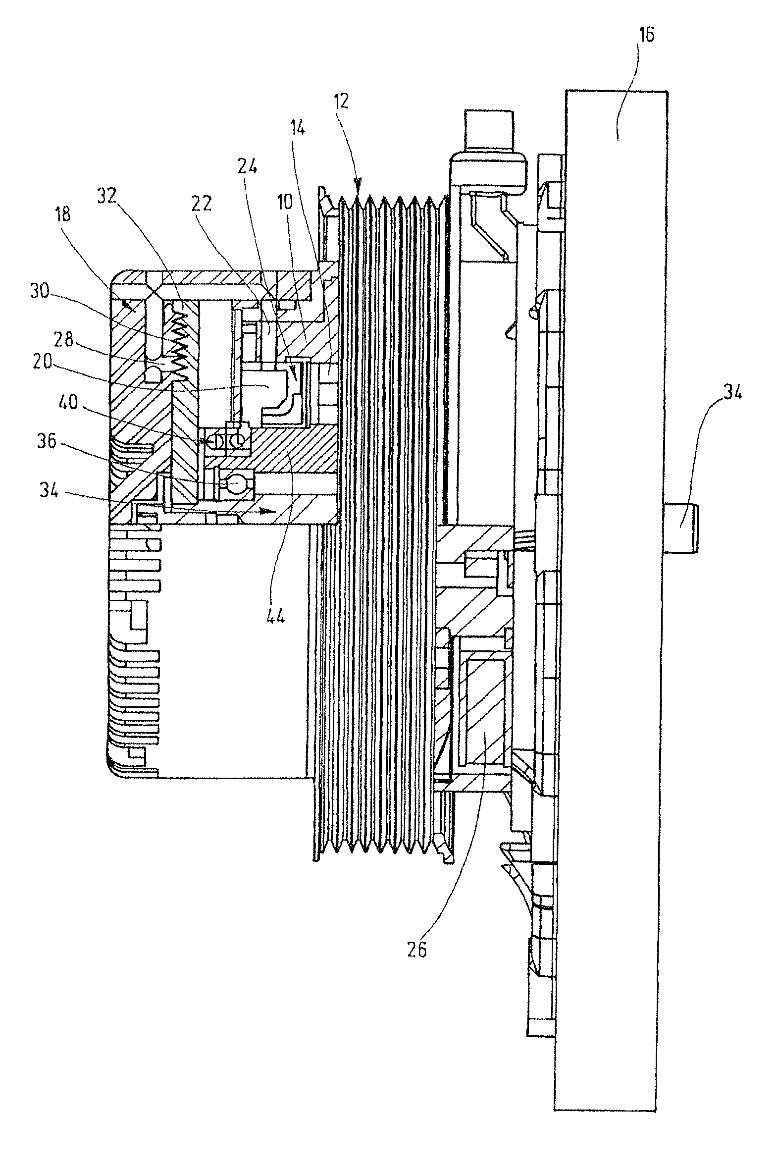
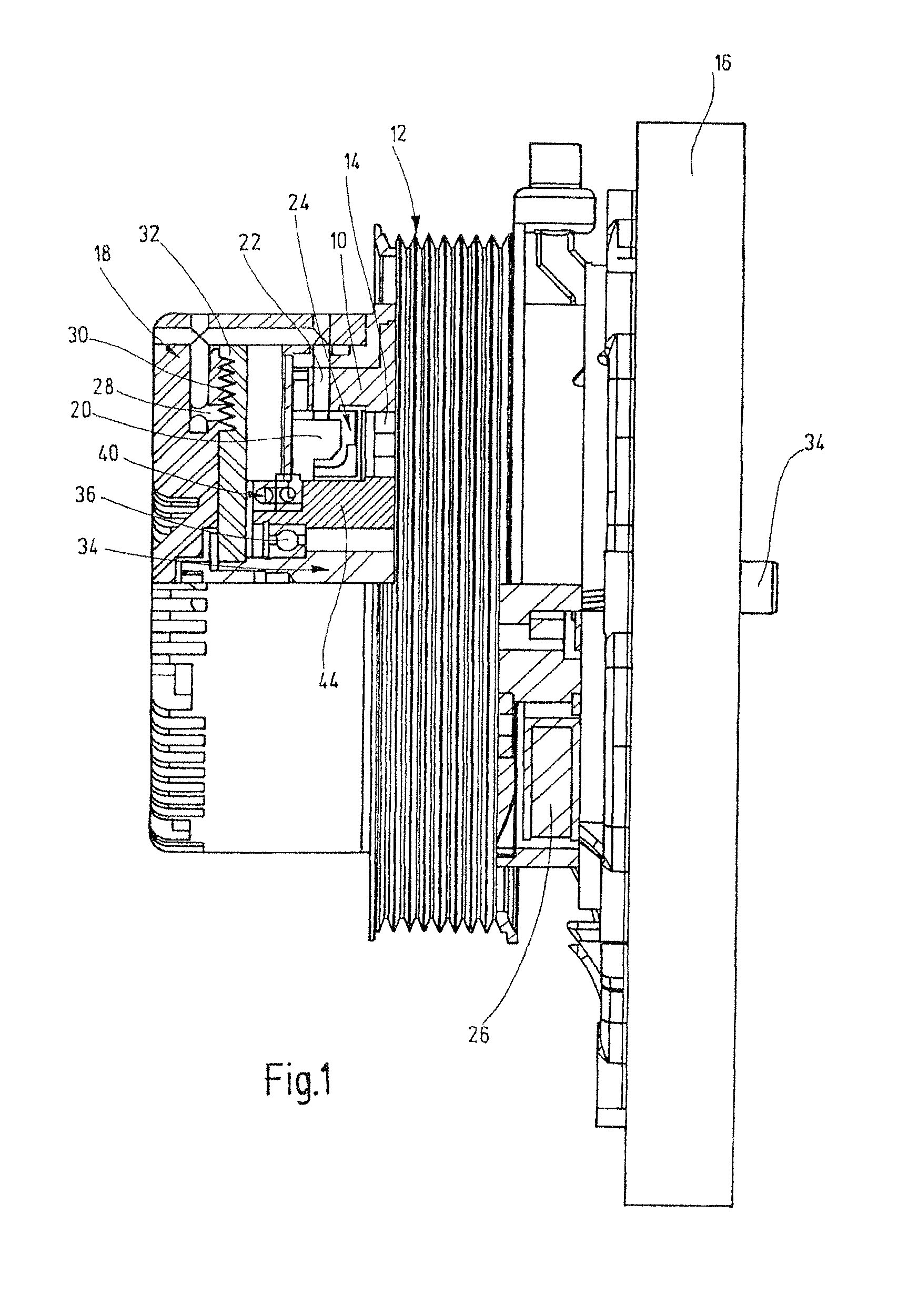
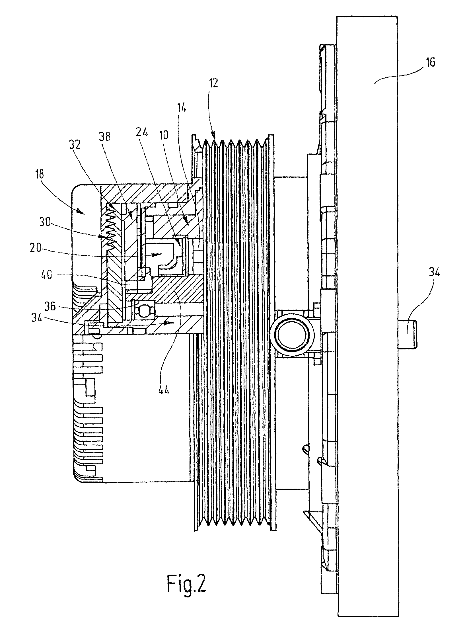
[0018]The clutch illustrated in FIGS. 1 and 2 has a housing with a housing body 10 and a housing cover 18. The housing body 10 supports a drive disk 12 which is driven by means of a poly-V-belt (not illustrated). The housing is rotatably arranged, by means of a bearing 14, on a stationary clutch member 16 which is, for example, fastened to an engine block (not shown). The cover 18 engages radially and partially axially over the housing body 10 and is fastened, for example screwed, thereto. Also situated in the housing is a reservoir chamber 20 for clutch fluid, for example, silicone oil. The reservoir chamber is connected to a supply duct 22 which leads radially outward, with it being possible for the passage cross section to the supply duct to be varied by means of a valve body 24. The valve body 24 is part of an electromagnetic valve arrangement and is actuated by means of an annular coil 26. The coil 26 is arranged on the stationary clutch part 16 and concentrically surrounds a h...


PUM


Abstract

A fluid friction clutch with improved fluid pumping system. A scraping member is provided adjacent the clutch plate and has a duct which communicates with the reservoir chamber.

Description


Claims


Application Information

Patent Timeline
Owner BORGWARNER INC
Why Eureka
Try Eureka