Hydraulically controlled cone disc continuously-variable transmission

a technology of cone disc and continuously variable transmission, which is applied in the direction of gearing control, multiple way valve, friction gearing, etc., can solve the problem of involuntary change of the position of the piston valv

Inactive Publication Date: 2011-06-07
PIV DRIVES
View PDF15 Cites 4 Cited by
  • Summary
  • Abstract
  • Description
  • Claims
  • Application Information

AI Technical Summary

Benefits of technology

[0015]It is therefore the aim of the present invention to prevent, in case of a failure, a sudden change command to an extreme gear ratio as described above, and to maintain the set-up gear ratio as much as possible, so that no overload of components and none of the other drawbacks or hazards as described above can occur.
[0019]On the one hand, this has the advantage that even in the event of a pump pressure failure, the clamping device will de-activated automatically without any additional separate elements being required. Besides, this type of construction is operationally very reliable.
[0026]The clamping could work here directly in the radial direction on the piston valve. But it is especially proposed to have the clamp bushing work on a piston rod coupled to the piston valve. This has the advantage that a separate component is provided for the clamping, thus avoiding the need to perform the clamping on sensitive surfaces of the piston valve.

Problems solved by technology

The disadvantage here is that because of a leakage in this hydraulic chamber it is still possible to experience an involuntary change of the position of the piston valve.

Method used


Image

  • Hydraulically controlled cone disc continuously-variable transmission
  • Hydraulically controlled cone disc continuously-variable transmission
  • Hydraulically controlled cone disc continuously-variable transmission

Examples


Embodiment Construction

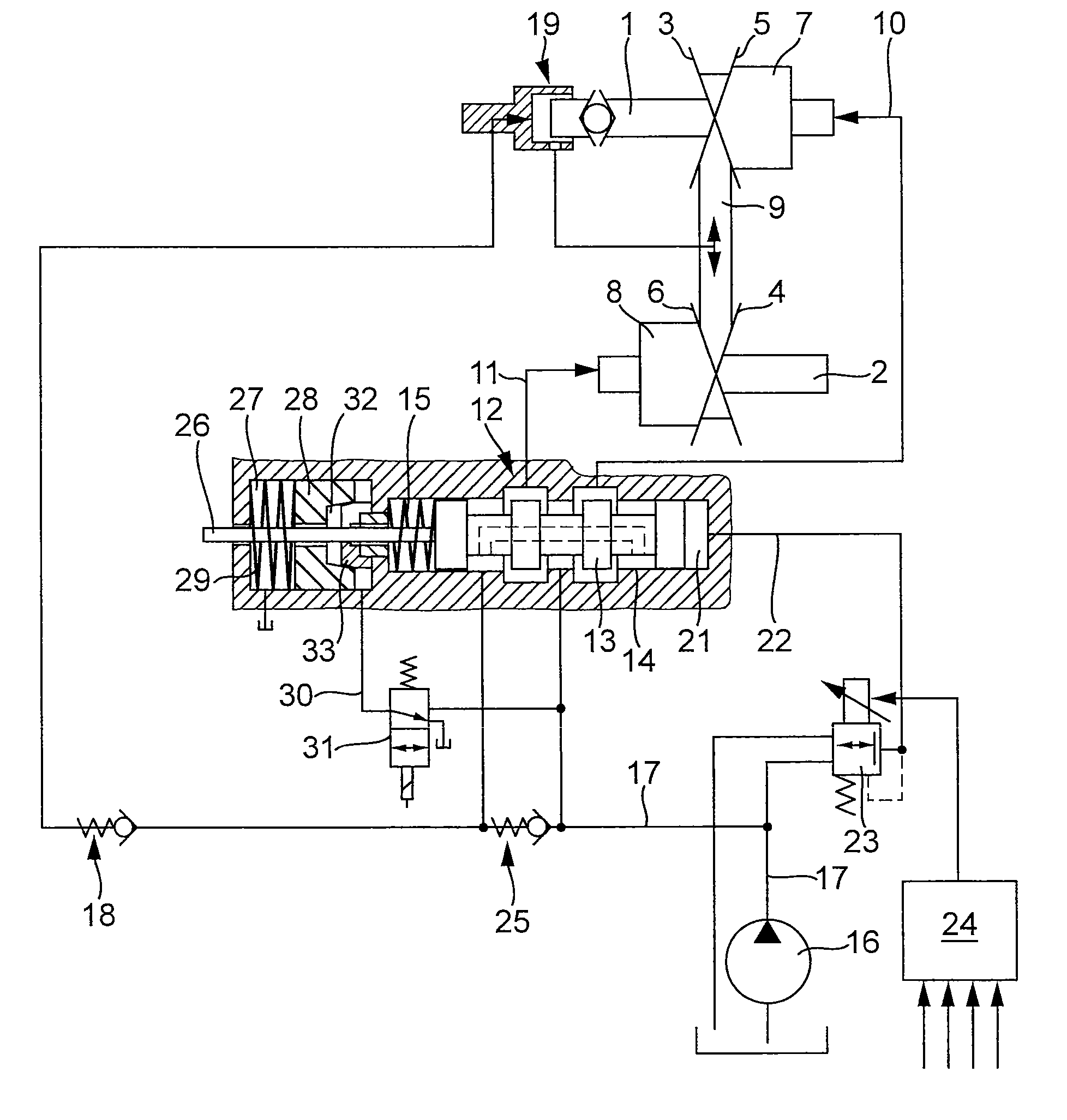
[0032]In FIG. 1, one identifies an infinitely-variable gearbox with two sets of discs arranged on two parallel shafts 1 and 2. These each consist of a cone disc 3 or 4 respectively, fixed to the shaft, and a cone disc 5 or 6 respectively that is torsionally connected with the shaft but that is axially slidable. The slidable cone discs 5 and 6 can be actuated by means of the corresponding pressure cylinders 7 or 8.

[0033]Both pairs of cone discs are frictionally connected to each other by a traction mechanism 9 that circulates between them.

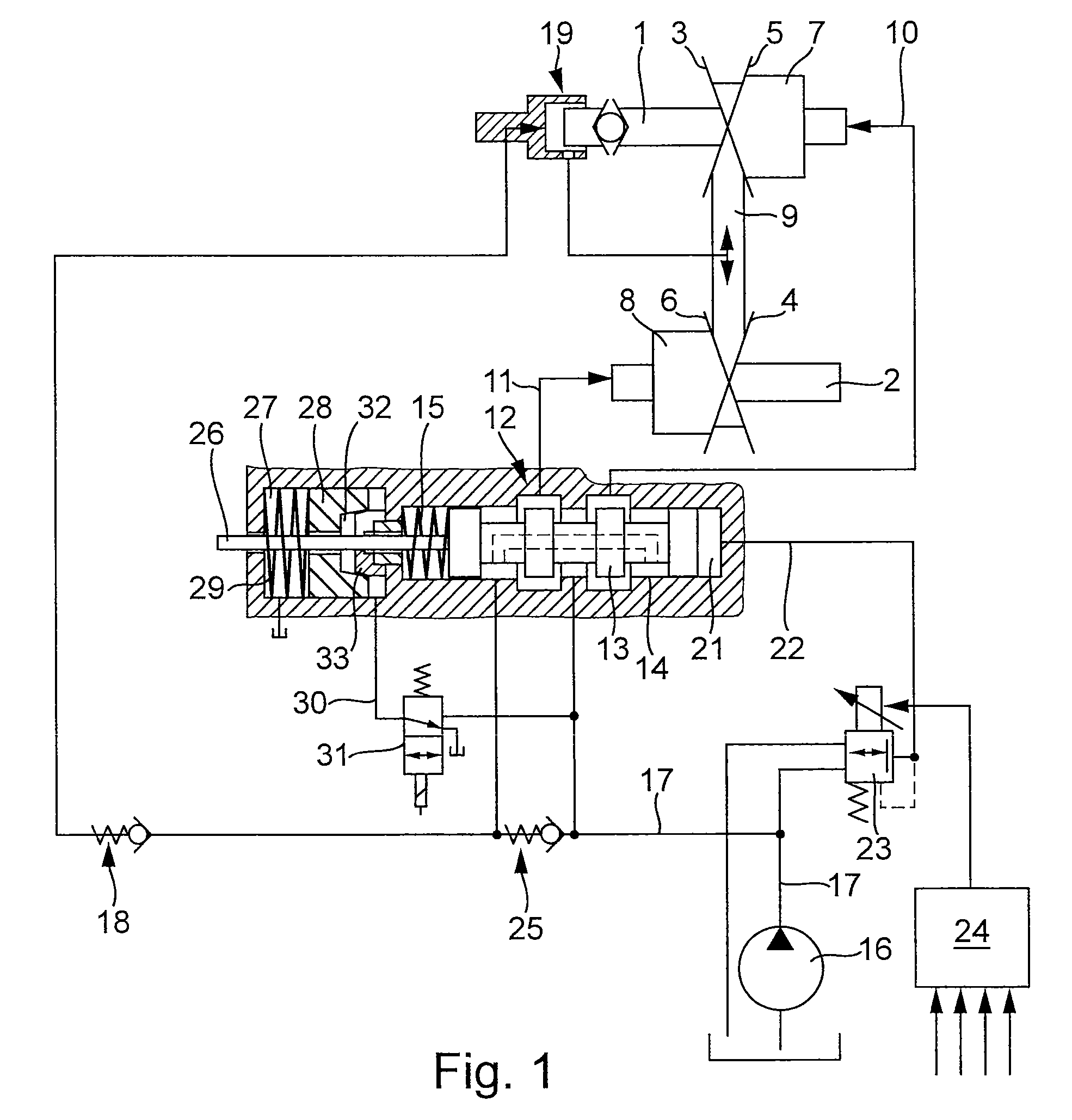
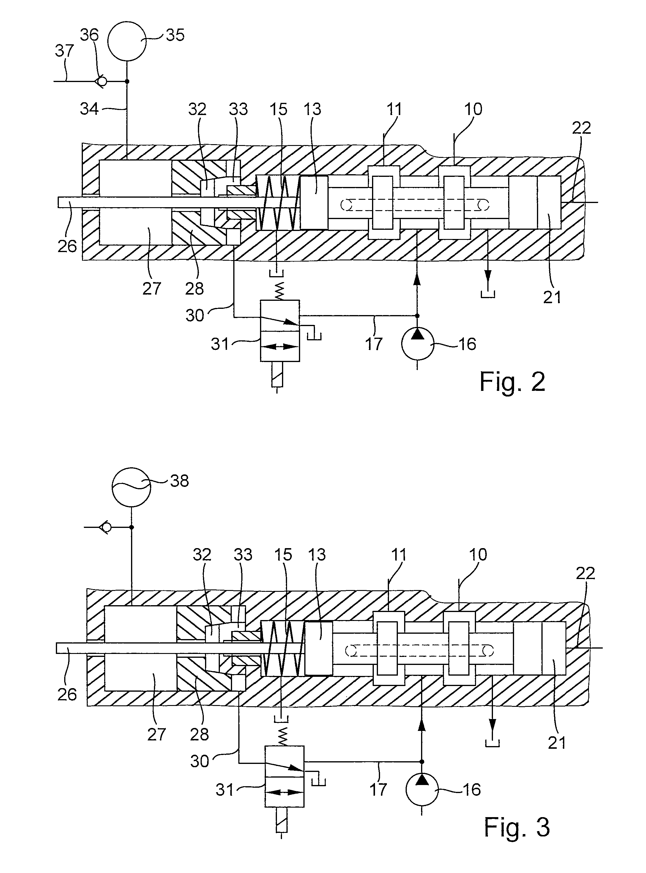
[0034]Through the conduits 10 and 11 the pressure cylinders 7 and 8 are provided with a pressure fluid from a control valve 12. This control valve is in the form of a so-called square spool valve, with a piston valve 13 being axially movable inside an appropriate housing 14 and resting against a spring element 15.

[0035]A pressure fluid is supplied to this control valve 12 by a pump 16 over a conduit 17. In order to maintain a desired base pressure, ...


PUM


Abstract

The invention concerns a continuously variable cone disc transmission with sets of discs mounted on drive and driven shafts. The sets of discs are each hydraulically adjustable axially in their distance from each other whereby the traction train circulating between them is able to adjust to different running circles and thereby enabling a continuously variable transmission. The pressure fluid needed for the hydraulic actuation is supplied to the pressure cylinders by a pump through a control valve. This control valve is actuated hydraulically by a pressure supply that is need-adjusted by a proportional-pressure reduction valve. In the event of a functional failure and consequent loss of the regulating pressure, the control valve is automatically arrested in position, so that the control valve is prevented from giving a command for the sudden change of the transmission ratio into an extreme position.

Description

CROSS-REFERENCE TO RELATED U.S. APPLICATIONS[0001]Not applicable.STATEMENT REGARDING FEDERALLY SPONSORED RESEARCH OR DEVELOPMENT[0002]Not applicable.NAMES OF PARTIES TO A JOINT RESEARCH AGREEMENT[0003]Not applicable.REFERENCE TO AN APPENDIX SUBMITTED ON COMPACT DISC[0004]Not applicable.BACKGROUND OF THE INVENTION[0005]1. Field of the Invention[0006]The invention concerns a cone disc continuously-variable transmission with pairs of cone discs mounted on drive and driven shafts, with one of the cone discs being fixed on the shaft and one of each being axially movable on the shaft, and between which a traction train circulates for power transfer. Together with pistons fixed on the shafts, the axially movable cone discs form cylinder-piston-aggregates. The cylinder-piston-aggregates are supplied by a pump via a control valve with a pressure medium for the setting and maintenance of the gear ratio. The control pressure actuating the control valve is determined as needed by a proportional...

Claims


Application Information

Patent Timeline
Patent Type & Authority Patents(United States)
IPC IPC(8): F16H59/00F16K11/044F16H61/12
CPCF16H61/12F16H61/66259Y10T477/6243F16H2061/1244
Inventor WAGNER, PETER
Owner PIV DRIVES
Why Eureka
Try Eureka