Image combining device and imaging apparatus

a technology of which is applied in the field of image combining device and imaging apparatus, can solve the problems of image degradation in the divided exposure image, and the first divided exposure image fixed as a reference image is not always the most suitable reference image,

Inactive Publication Date: 2011-06-07
XACTI CORP
View PDF16 Cites 3 Cited by
  • Summary
  • Abstract
  • Description
  • Claims
  • Application Information

AI Technical Summary

Problems solved by technology

However, a plurality of divided exposure images may include a divided exposure image with significant image blur caused by camera shake or moving subject.
However, the first divided exposure image fixed as a reference image is not always the most suitable reference image.
This coordinate transformation generally entails interpolation of pixel values, resulting in some image degradation in the divided exposure images other than the reference image.

Method used


Image

  • Image combining device and imaging apparatus
  • Image combining device and imaging apparatus
  • Image combining device and imaging apparatus

Examples


first embodiment

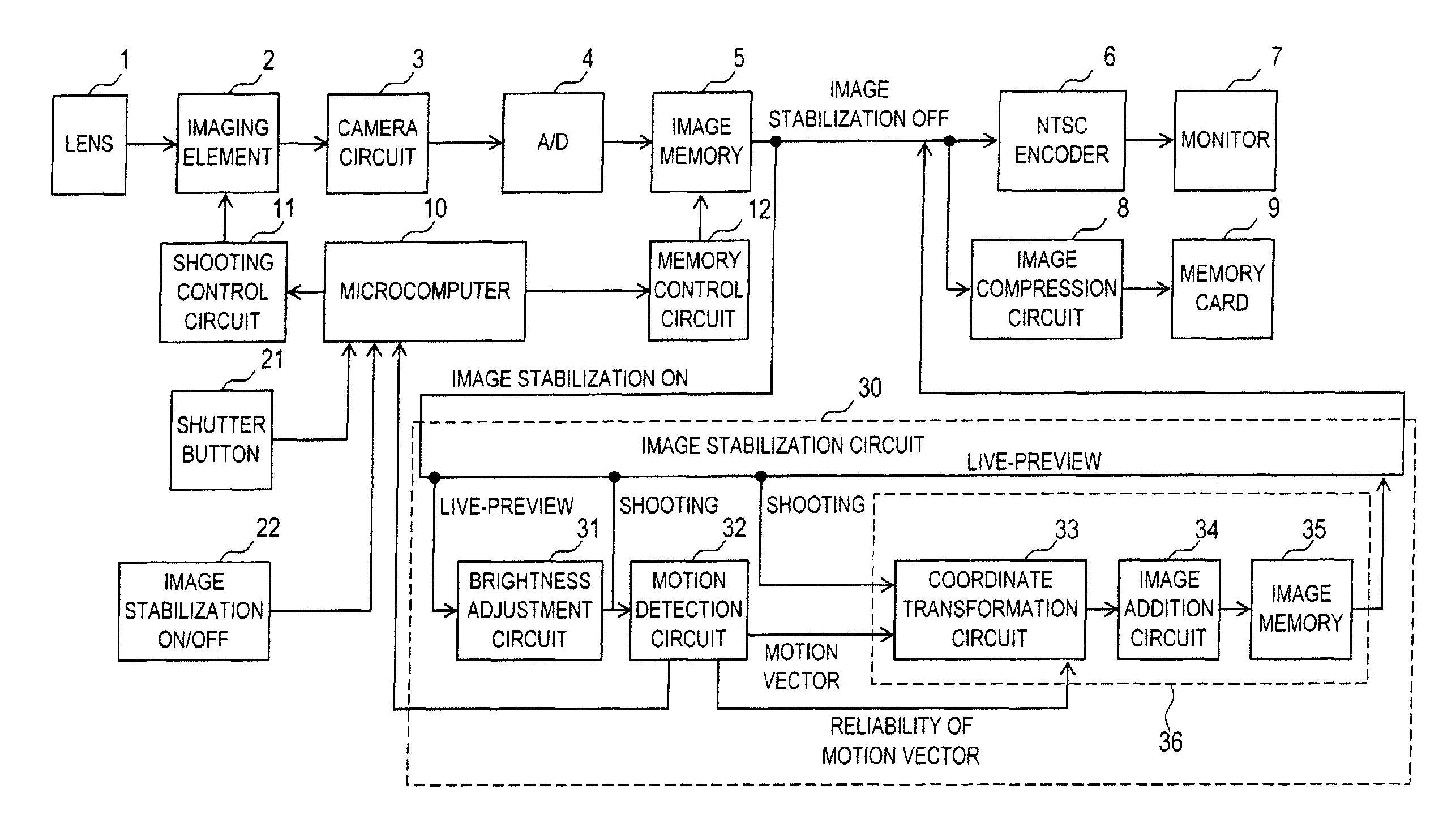
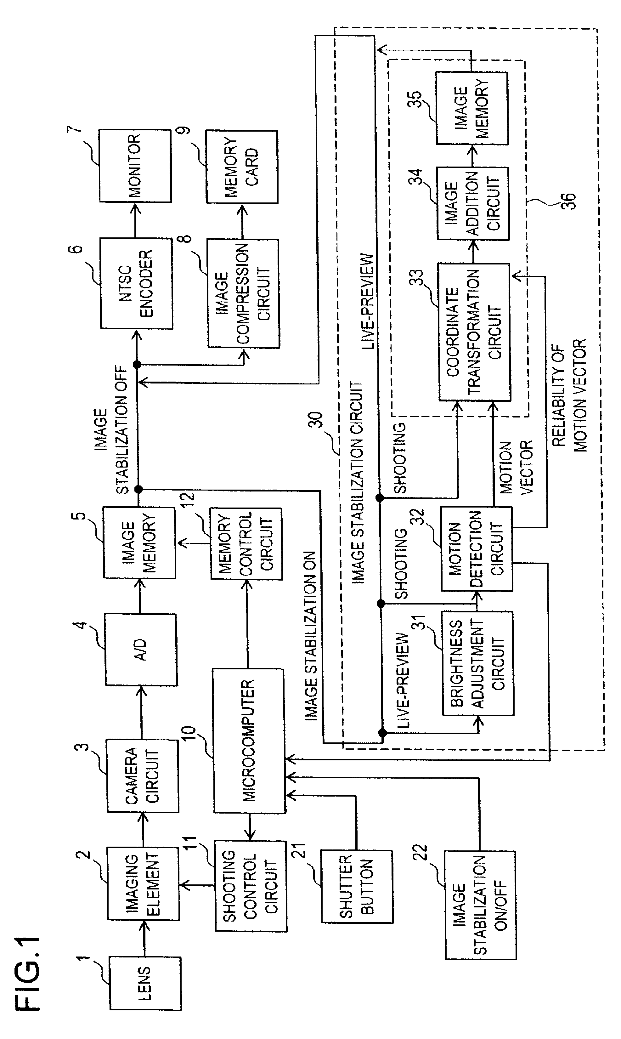
[0055]Hereinafter, a first embodiment will be described by way of an example in which the present invention is applied to an imaging apparatus. FIG. 1 is a diagram showing the entire configuration of an imaging apparatus according to the first embodiment of the present invention. The imaging apparatus shown in FIG. 1 is, for example, a digital still camera or a digital video camera, and can take at least a still image. The imaging apparatus shown in FIG. 1 is composed of different component blocks represented by reference numerals 1 to 12, 21, 22, and 30. An image stabilization circuit represented by reference numeral 30 includes a brightness adjustment circuit 31, a motion detection circuit 32, a coordinate transformation circuit 33, an image addition circuit 34, and an image memory 35. The coordinate transformation circuit 33, the image addition circuit 34, and the image memory 35 together form an image combining circuit 36. In the following description, what is referred to simply...

second embodiment

[0185]The first embodiment described above deals with a case in which the level of reliability B[i] is calculated with consideration given to all of the four evaluation values (BVmin[i], BVave[i], BNf[i], and BNval[i]). Alternatively, it is also possible to calculate the level of reliability B[i] with consideration given only to one, two, or three of the four evaluation values. In other words, any one, two, or three of the weighting coefficients WVmin, WVave, WNf, and WNval may be set equal to zero (see formula (2) above). In this case, it is possible to omit the calculation of the evaluation value multiplied by a weighting coefficient of zero in formula (2) above.

[0186]A second embodiment deals with an example in which the level of reliability B[i] is calculated by using only the evaluation value BVmin[i] corresponding to the smallest cumulative total correlation value. The second embodiment differs from the first embodiment only in that the level of reliability B[i] is calculated ...

third embodiment

[0189]The first and second embodiments deal with cases in which the first divided exposure image (the first image) of a plurality of divided exposure images obtained when the shutter button 21 is depressed is used as a reference image, based on which the calculation of the entire motion vector M and the positioning of the divided exposure images are performed; however, any of the plurality of divided exposure images may be used as a reference image.

[0190]Furthermore, a divided exposure image used as a reference image may be changed according to the values described above, such as Vmin. A third embodiment deals with a method for changing the reference image. The third embodiment is a partially modified version of the first embodiment, and all the features described in the first embodiment can be applied, unless inconsistent, to the third embodiment. For the sake of concreteness, as is the case with the first embodiment, the third embodiment also deals with a case in which four divide...


PUM


Abstract

A plurality of divided exposure images (first to fourth images) are obtained by dividing a normal exposure time. By an image matching method, a motion detection circuit calculates a plurality of cumulative total correlation values between different divided exposure images, and searches the plurality of cumulative total correlation values for the smallest cumulative total correlation value, thereby calculating a motion vector between the different divided exposure images. In addition, based on the level of the smallest cumulative total correlation value, the level of reliability B[i] indicating the accuracy of the motion vector is calculated. An image combining circuit uses the level of reliability B[i] as a mixture proportion. The image combining circuit positions the divided exposure images based on the motion vector, and combines the divided exposure images together one on top of another in mixture proportions (B[i]), so as to form one still image that suffers less from camera shake.

Description

[0001]This nonprovisional application claims priority under 35 U.S.C. §119(a) on Patent Application No. 2006-235671 filed in Japan on Aug. 31, 2006, the entire contents of which are hereby incorporated by reference.BACKGROUND OF THE INVENTION[0002]1. Field of the Invention[0003]The present invention relates to image combining devices that combine a plurality of images and to image combining methods for combining a plurality of images. The present invention also relates to imaging apparatuses that adopt such image combining devices or image combining methods.[0004]2. Description of Related Art[0005]In recent years, an image stabilization technique, which is a technique for reducing camera shake when shooting with a camera, has been actively studied. Irrespective of whether a stabilization target is a still image or a moving image, the image stabilization technique can be broken down into a technique for detecting camera shake and a technique for stabilizing an image based on the dete...

Claims


Application Information

Patent Timeline
Patent Type & Authority Patents(United States)
IPC IPC(8): H04N5/228
CPCG06T5/50G06T7/0024H04N5/23232H04N5/23248H04N5/23267H04N5/23277G06T5/003H04N5/23254G06T2207/20201G06T7/30H04N23/951H04N23/68H04N23/6811H04N23/683H04N23/6845
Inventor HATANAKA, HARUOIIDA, TAKASHI
Owner XACTI CORP
Why Eureka
Try Eureka