Suspension having a trace bent part that is fixed to a tongue part and an outrigger part

a trace bent and suspension technology, applied in the direction of head support, record information storage, instruments, etc., can solve the problems of insufficient positioning accuracy of magnetic head provided by such a control, prompt and appropriate flying cannot be realized, etc., to improve the inline stiffness of the suspension, improve and increase the low pitch/roll stiffness of the tongue part

Inactive Publication Date: 2011-06-07
SAE MAGNETICS (HK) LTD
View PDF14 Cites 11 Cited by
  • Summary
  • Abstract
  • Description
  • Claims
  • Application Information

AI Technical Summary

Benefits of technology

[0025]The present invention is configured and works as described above. With this configuration, at least a part of a bent part in which the strength of the trace is high is fixed to the tongue part, so the stiffness in a longitudinal direction (inline stiffness) of the tongue part formed to realize low pitch / roll stiffness is increased by the trace. Accordingly, the present invention can exhibit an excellent effect of realizing low pitch / roll stiffness of the tongue part while improving the inline stiffness of the suspension, which has not been achieved conventionally.

Problems solved by technology

In recent years, however, due to an increase in recording density of a magnetic disk, positioning accuracy of a magnetic head provided by such a control is not sufficient.
In such a case, if using a CSS drive of the type which causes the magnetic head slider placed on a magnetic disk to fly along with the rotation of the magnetic disk, the magnetic head slider mounted on the tongue part is drawn along with the rotation of the magnetic disk to thereby be stuck to the magnetic disk, causing a problem that prompt and appropriate flying cannot be realized.

Method used


Image

  • Suspension having a trace bent part that is fixed to a tongue part and an outrigger part
  • Suspension having a trace bent part that is fixed to a tongue part and an outrigger part
  • Suspension having a trace bent part that is fixed to a tongue part and an outrigger part

Examples


second embodiment

nsions carried out in the second embodiment;

[0046]FIG. 17A is a diagram showing the configuration of a suspension used in simulation in the second embodiment;

[0047]FIG. 17B is a diagram showing the configuration of a suspension used in simulation in the second embodiment;

[0048]FIG. 17C is a diagram showing the configuration of a suspension used in simulation in the second embodiment;

[0049]FIG. 18 is a table showing the simulation results for the characteristics of the suspensions carried out in the second embodiment;

[0050]FIG. 19 is a graph showing the simulation results for the characteristics of the suspension carried out in the second embodiment;

[0051]FIG. 20 is a graph showing the simulation result for the characteristics of the suspension carried out in the second embodiment;

[0052]FIG. 21 is a diagram showing the configuration of a suspension according to a third embodiment;

[0053]FIG. 22 is a diagram showing another configuration of a suspension according to the third embodimen...

embodiment 1

[0056]A first embodiment of the present invention will be described with reference to FIGS. 4 to 8. FIGS. 4 and 5 are diagrams showing the configuration of a head gimbal assembly of the present embodiment, and FIGS. 6 and 7 are enlarged views showing the configuration of a flexure and a trace. FIG. 8 shows data indicating the characteristics of the flexure of the present embodiment.

[Configuration]

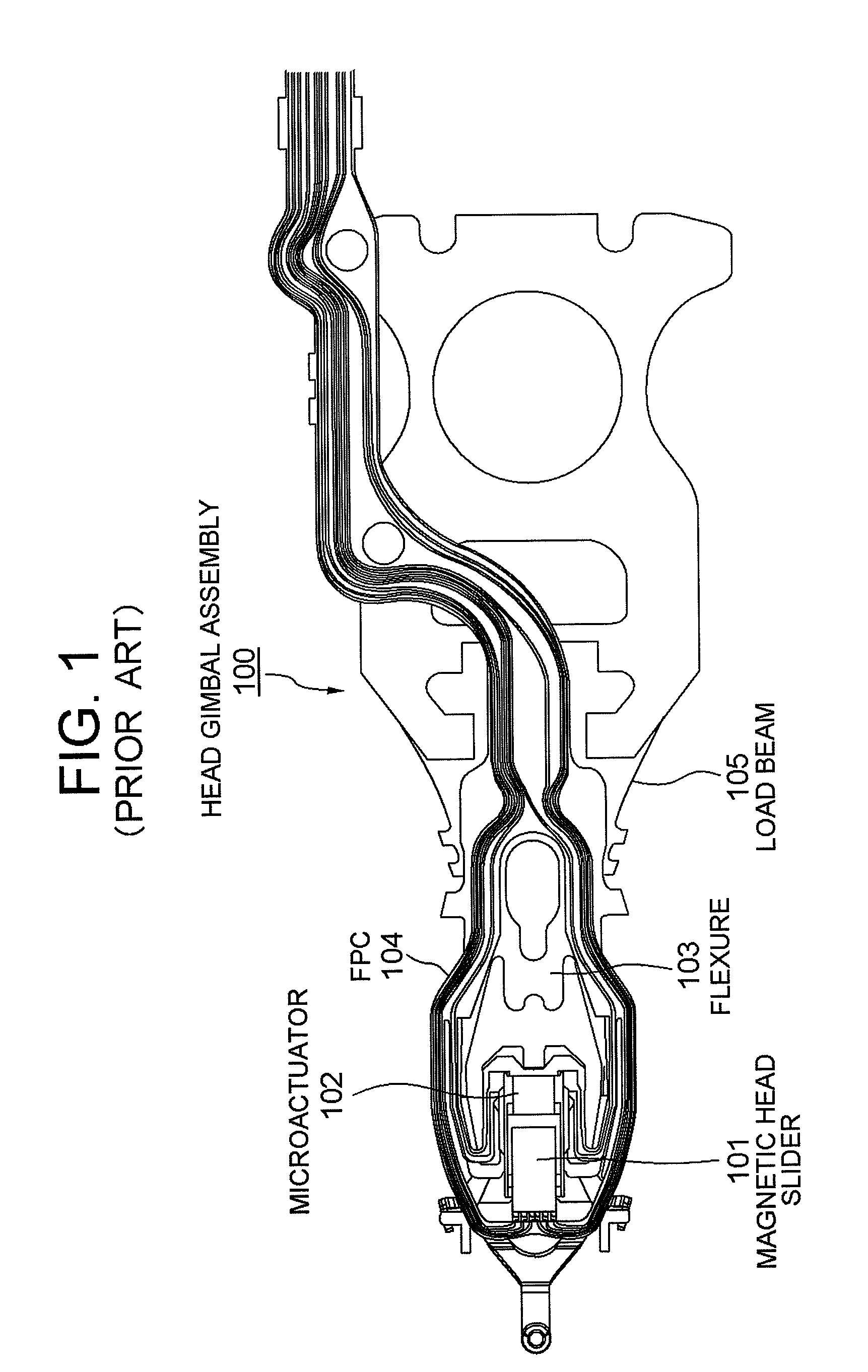
[0057]FIGS. 4 and 5 show an exemplary configuration of a head gimbal assembly 10 to be mounted on a disk drive of the present embodiment. FIG. 4 shows a side view, and FIG. 5 shows a front view of FIG. 4 viewed from underneath (magnetic disk facing face).

[0058]As shown in FIGS. 4 and 5, the head gimbal assembly 10 includes: a magnetic head slider 1; a microactuator 2 holding the magnetic head slider 1 between the arms thereof so as to precisely drive the slider 1; a flexure 3 having a spring property, in which the magnetic head slider 1 and the microactuator 2 are mounted on the tip part th...

embodiment 2

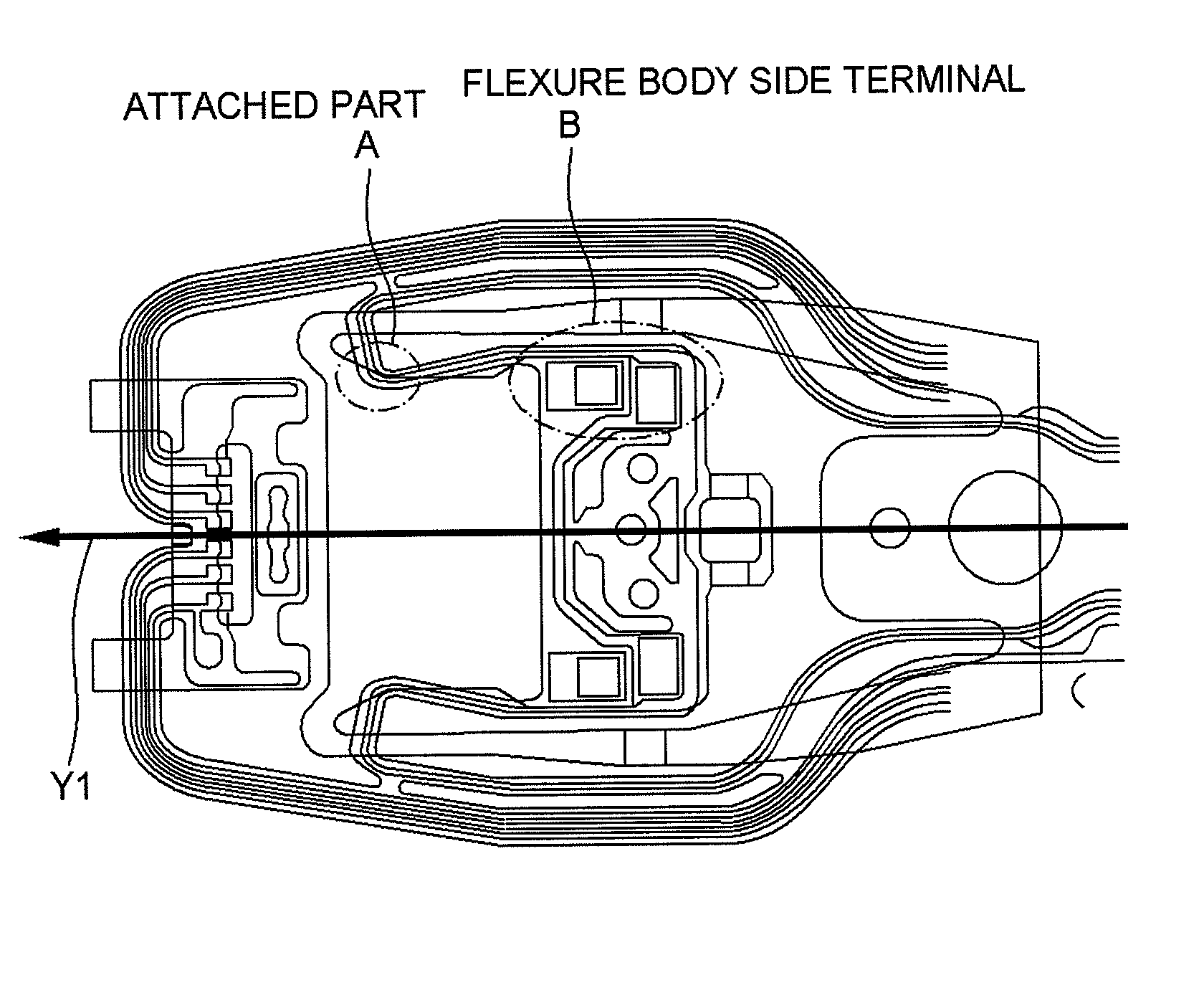
[0070]Next, description will be given for simulation results carried out by changing the position and the area of the attached part A (fixed part between the flexure 3 and the trace 4) in the suspensions 3 and 4 having the configuration described above so as to find out appropriate values thereof.

[0071]First, description will be given with reference to FIGS. 9A to 12. FIGS. 9A, 9B, 10A, and 10B show suspensions 3 and 4 of different shapes designed by changing the attached area between the trace 4 (trace 42 for actuator) and the tongue part B in the attached part A. For convenience, the configuration shown in FIG. 9A is referred to as a model 1, and the configuration shown in FIG. 10A is referred to as a model 3. FIGS. 9A and 10A show plan views, and FIGS. 9B and 10B show enlarged views of the surrounding part a of the attached part A. Besides them, models 2 and 4 of different shapes were also prepared and simulations were carried out, but the models 2 and 4 are not shown.

[0072]As sh...


PUM

PropertyMeasurementUnit
lengthaaaaaaaaaa
distanceaaaaaaaaaa
recording densityaaaaaaaaaa

Abstract

A suspension is provided for improving reliability in reading / writing of data by improving stiffness in a longitudinal direction of a flexure while realizing low pitch / roll stiffness of a tongue part. The suspension includes: a flexure, including two branched outrigger parts extending to the tip side of the flexure, and a tongue part for mounting a magnetic head slider, located between the outrigger parts and linked to the tip sides of the outrigger parts; a trace formed on the flexure; and a fixed part in which at least a part of a bent part formed in the trace is fixed to the tongue part.

Description

BACKGROUND OF THE INVENTION[0001]1. Field of the Invention[0002]The present invention relates to a suspension, and in particular, to a suspension on which a magnetic head slider is mounted. Further, the present invention relates to a head gimbal assembly and a disk drive using the suspension.[0003]2. Description of Related Art[0004]A hard disk drive, which is data storage, includes a head gimbal assembly equipped with a magnetic head slider performing read / write of data to a magnetic disk which is a storage medium. FIG. 1 shows a conventional example of a head gimbal assembly 100.[0005]The head gimbal assembly 100 includes: a magnetic head slider 101; a flexure 103 having a spring property equipped with the magnetic head slider 101 on the tip part thereof; an FPC 104 (flexible printed circuit) formed on the flexure 103, which transmits signals to the magnetic head slider 101; and a load beam 105 supporting the flexure. The load beam 105 is mounted on a head arm via a base plate not ...

Claims


Application Information

Patent Timeline
Patent Type & Authority Patents(United States)
IPC IPC(8): G11B21/21
CPCG11B5/486G11B5/4853G11B5/4826G11B5/4833Y10T29/49025G11B5/5552
Inventor MATSUI, HIDETOSHIHONDA, TAKASHIWADA, YOSHIMITSU
Owner SAE MAGNETICS (HK) LTD
Why Eureka
Try Eureka