Pivot mechanism and electronic device applying the same

a technology of pivot mechanism and electronic device, which is applied in the direction of wing accessories, instruments, and portable computers, etc., can solve the problems of reducing the life of the pivot mechanism, and affecting the operation of the devi

Inactive Publication Date: 2011-06-14
FIRST DOME
View PDF8 Cites 27 Cited by
  • Summary
  • Abstract
  • Description
  • Claims
  • Application Information

AI Technical Summary

Benefits of technology

[0008]Accordingly, the present invention is directed to a pivot mechanism capable of performing reliable rotation and providing locating effect in various orientations.
[0017]According to the aforementioned embodiment, a width of an annular body of each annular reed may be gradually decreased from the locating portion to the first position limiting portion.

Problems solved by technology

Therefore, design of the pivot mechanism affects the convenience for a user to operate the aforementioned devices and the reliability of the aforementioned devices.
For example, an exceeding friction between the stator and the rotor leads to a laborious pivot operation, which causes wear of the pivot mechanism and reduces the life time of the pivot mechanism.
On the other hand, an insufficient friction leads to a loose fit between the stator and the rotor, which fails to provide an effective locating and may damage the devices when applying an improper loading.
Furthermore, an improper fit of elements of the pivot mechanism may generate a reacting force between the rotor and the stator in the pivoting process, and when the user removes the loading applied on the pivot mechanism, the body connected to the pivot mechanism cannot reach a predetermined position precisely due to the effect of the reacting force.

Method used


Image

  • Pivot mechanism and electronic device applying the same
  • Pivot mechanism and electronic device applying the same
  • Pivot mechanism and electronic device applying the same

Examples


Embodiment Construction

[0033]Reference will now be made in detail to the present preferred embodiments of the invention, examples of which are illustrated in the accompanying drawings. Wherever possible, the same reference numbers are used in the drawings and the description to refer to the same or like parts.

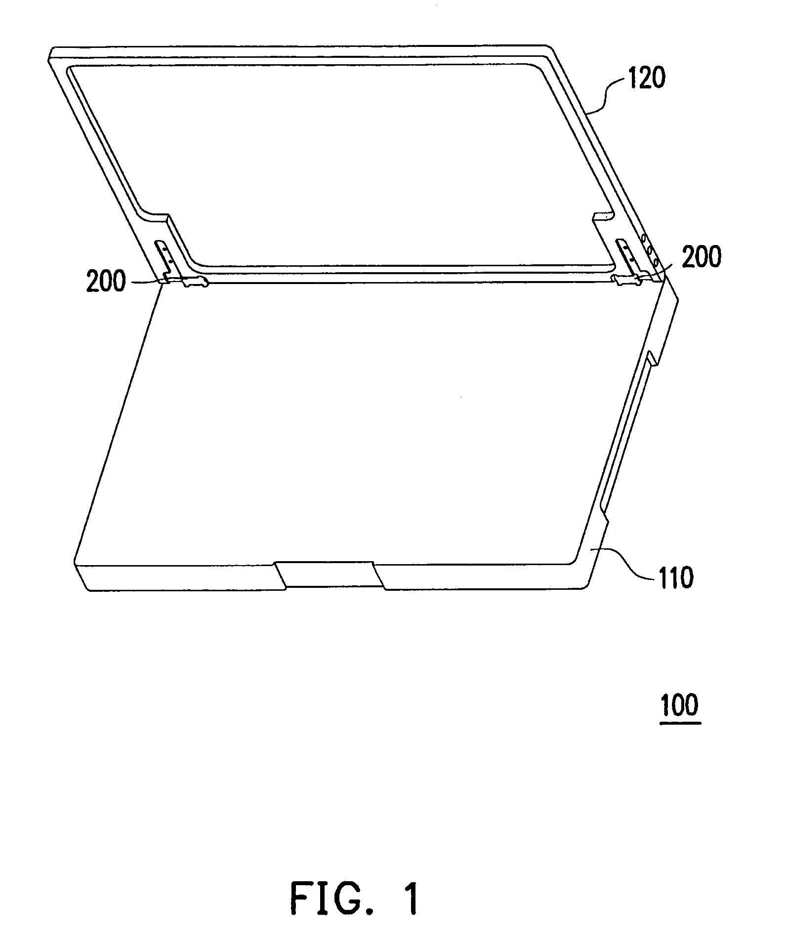
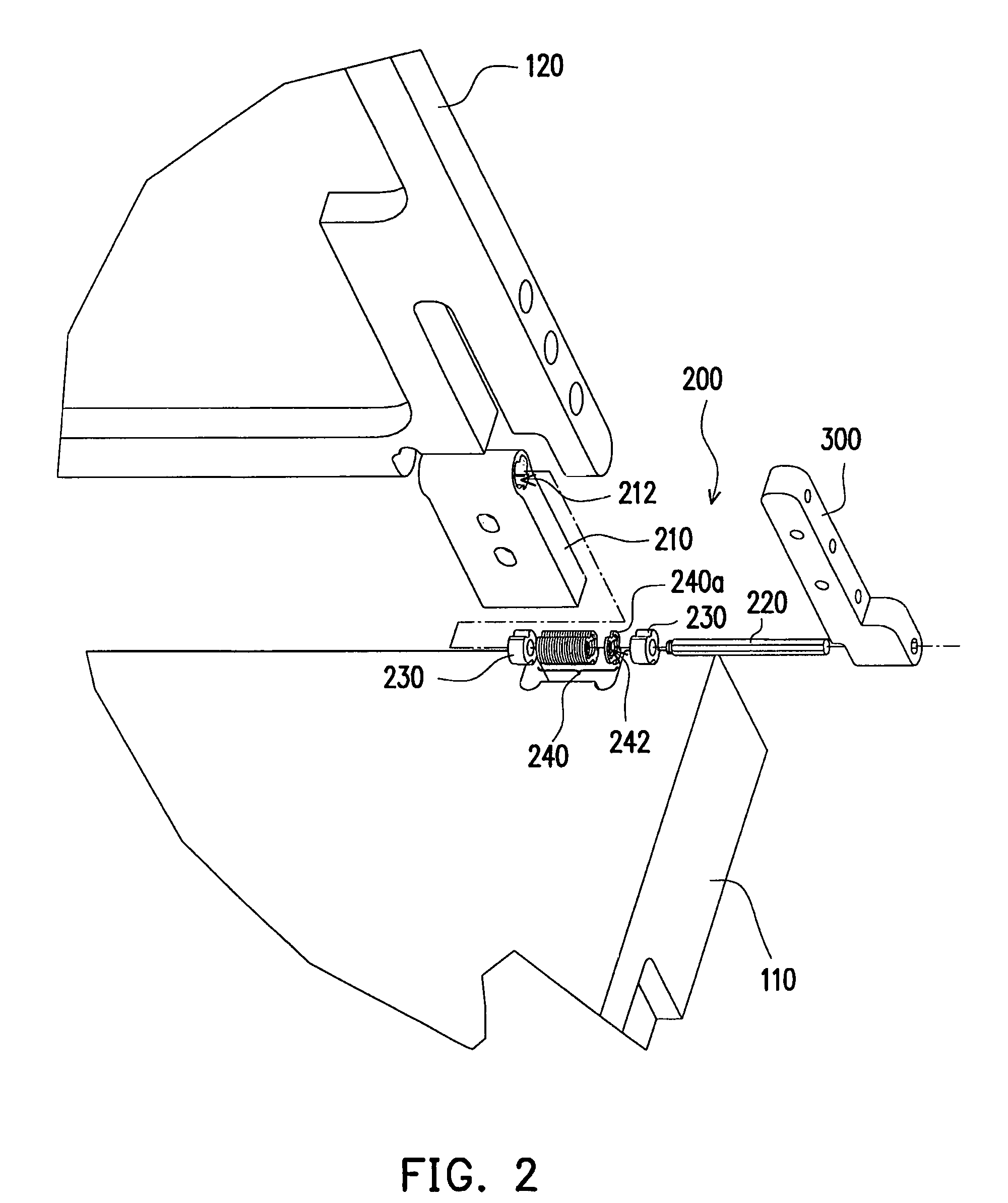
[0034]The pivot mechanism of the invention can be applied to various devices to perform a reliable and convenient rotation and provides locating effect in different orientations. For example, doors, windows, reflecting mirrors of vehicles, or electronic devices such as notebooks, electronic dictionaries, personal digital assistants (PDA), or mobile phones often seen in our daily life are suitable for the pivot mechanism.

[0035]A notebook of the electronic devices is taken as an example for illustrating the details and advantages of the pivot mechanism of the invention. However, people skilled in the art may refer to the following embodiments and transfer the pivot mechanism of the invention to any app...


PUM


Abstract

A pivot mechanism and an electronic device applying the same are provided. The pivot mechanism includes a pedestal having a bore passing through the pedestal; a shaft inserted into the bore and having at least two leaning surfaces in parallel to an extending direction of the shaft; two bushes coupled to the shaft and fixed in the bore; and a reed set disposed in the bore and arranged between the two bushes. The reed set includes at least one reed, wherein each reed is wedged in the bore and has a hole through which the shaft penetrates. At least one position limiting portion is formed in the periphery of the hole for orienting the shaft. The position limitation portion further extends inwardly to form a slot, by which a cantilever is formed between the slot and the axis hole to lean against the shaft.

Description

CROSS-REFERENCE TO RELATED APPLICATION[0001]This application claims the priority benefit of Taiwan application serial no. 97145322, filed on Nov. 24, 2008. The entirety of the above-mentioned patent application is hereby incorporated by reference herein and made a part of this specification.BACKGROUND OF THE INVENTION[0002]1. Field of the Invention[0003]The present invention generally relates to a pivot mechanism and an electronic device applying the pivot mechanism. More particularly, the present invention relates to the pivot mechanism and the electronic device capable of performing reliable rotation and providing locating effect in various orientations.[0004]2. Description of Related Art[0005]In our daily life, various devices including doors, windows, reflecting mirrors of vehicles, or electronic devices such as notebooks, electronic dictionaries, personal digital assistants (PDA), or mobile phones apply pivot mechanisms to perform a rotation or switch on / off. The conventional p...

Claims


Application Information

Patent Timeline
Patent Type & Authority Patents(United States)
IPC IPC(8): E05D11/08
CPCG06F1/1616G06F1/1681E05D11/082E05Y2900/606Y10T16/5406Y10T16/557Y10T16/54038
Inventor KUO, CHUNG-CHICHANG, CHI-PU
Owner FIRST DOME
Why Eureka
Try Eureka