
Decorative pole and base stand stabilizing container

a technology for stabilizing containers and decorative poles, which is applied in the field of decorative poles and stabilizers, can solve the problems of reducing the stability of the base stand, affecting the stability of the container, so as to reduce the wobbling of the base stand and discourage accidental bumping

Inactive Publication Date: 2011-06-14
KAMAU MARIA N
View PDF4 Cites 15 Cited by
  • Summary
  • Abstract
  • Description
  • Claims
  • Application Information

AI Technical Summary

Benefits of technology

"The present invention provides a container that stabilizes a freestanding fixture by minimizing wobbling of the base stand once the fixture is bumped. The container includes a sidewall and a base panel that integrally attach to each other to form a ballast volume, a pole void, and a base void. The container can be easily assembled and disassembled, and it does not require screws, nails, clips, or brackets to stabilize the fixture. The container can be adapted to various freestanding fixtures, and it can be used in both indoor and outdoor settings. The container is economical, aesthetically pleasing, and it can be mass-produced. The container is also easy to assemble and disassemble, and it does not require disassembling the fixture. The container can be separated into an upper planter section and a lower reservoir section, and it can include a wedge section to detachably close off the wedge void. The container is constructed of a solid material, so it can hold ballast, soil, water, or other material without the need of a plastic liner or other lining material."

Problems solved by technology

Often the base stands provided with such fixtures have at least one if not both of the following problems.
Firstly, the base stands are too small or too lightweight to offer sufficient stability from accidental tip-over if bumped.
Secondly, the base stands are often aesthetically incompatible with the home or office décor.
This method tends to clutter and crowd floor space, thus creating a trip hazard.
Also, this method tends to be expensive if base stands of several freestanding fixtures in a room need contact buffers or need visual alternatives created around them.
This creates aesthetic disharmony in a given room or outdoor setting.
U.S. Pat. No. 6,615,543 to Palsrok discloses a wire basket arrangement held together by wires, which is not capable, absent a liner or other material, of holding soil, ballast, or other material.
U.S. Pat. Application 2004 / 0216376 to Missry discloses a planter device, but the design would make it difficult or impossible to position around a freestanding fixture with pole and a base without disassembling the pole from the base.
Until now, prior art planter inventions have failed to simultaneously stabilize, aesthetically harmonize, and decorate freestanding fixtures.
The aforementioned inventions could not be useful in stabilizing and concealing a base stand of a freestanding fixture.
In fact, some of the aforementioned prior art aggressively seek stability from the pole or post of a fixture itself by means of nails, brackets, clips, or other permanent attachments.
To create a contact buffer, Teixeira's invention would require an assembly of several units; even so, this would still not stabilize the base stand of a freestanding fixture.
In addition, using multiple planter units arrayed about a freestanding fixture would pose a trip hazard or crowd and clutter floor space.
The vertical uniformity of the gap illustrates the inability of these prior art devices to substantially surround the lower portion of a pole and the entire base stand of a device such as a floor lamp.
Even if these two prior art devices were made large enough to envelop both the pole and base stand of a floor lamp, for instance, the resulting massive lateral u-shaped gap would not provide ornamentation or stability to the base stand of a freestanding fixture such as a floor lamp.
Consequently, if the fixture was bumped, Carson's and Hammond's inventions would not restricts lateral movement of the base stand enough to deter the fixture from overturning if the fixture were to fall in a direction aligned with the gap.

Method used


Image

  • Decorative pole and base stand stabilizing container
  • Decorative pole and base stand stabilizing container
  • Decorative pole and base stand stabilizing container

Examples


third embodiment

Alternate Third Embodiment

FIGS. 3a, 3b

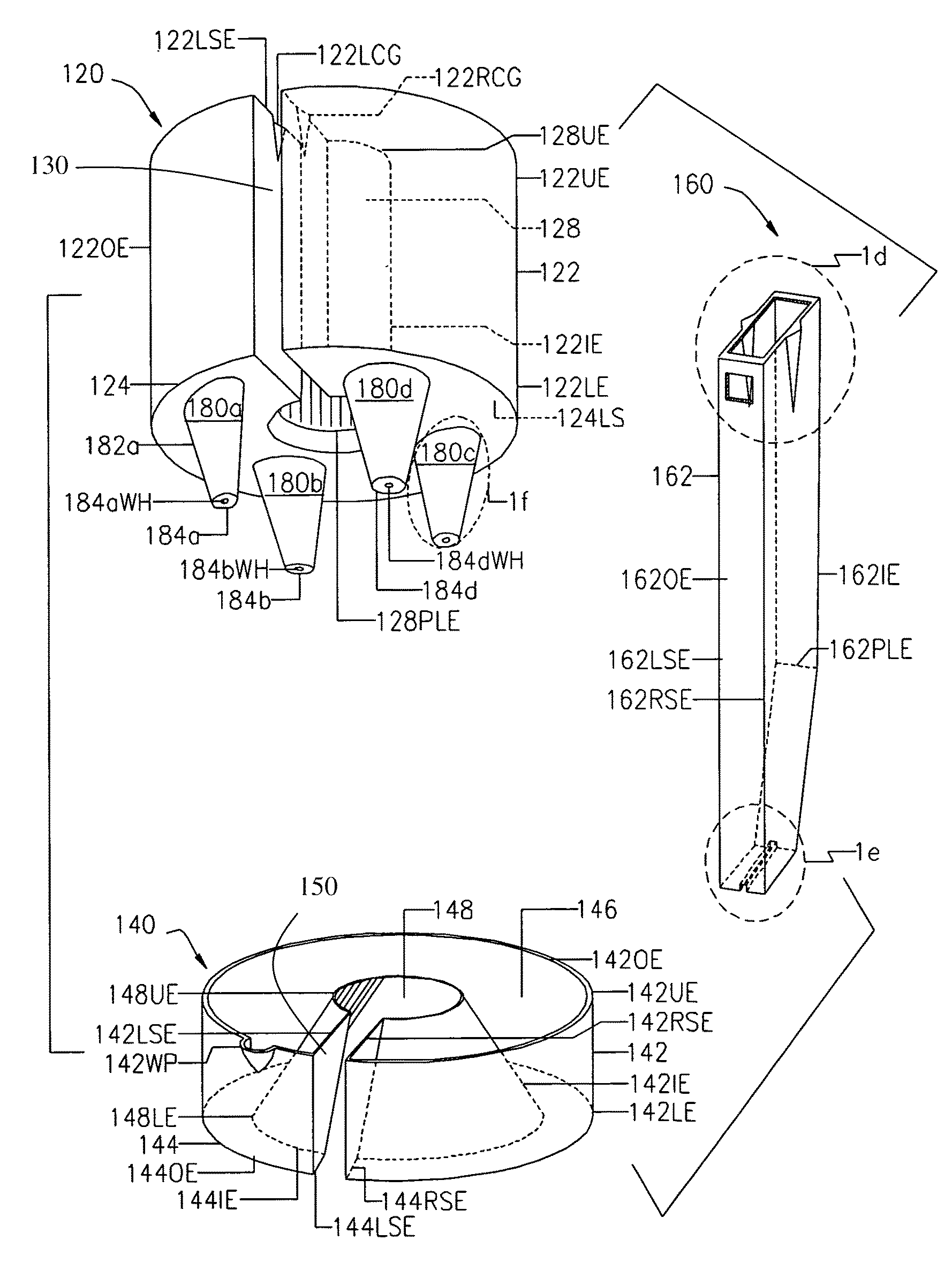
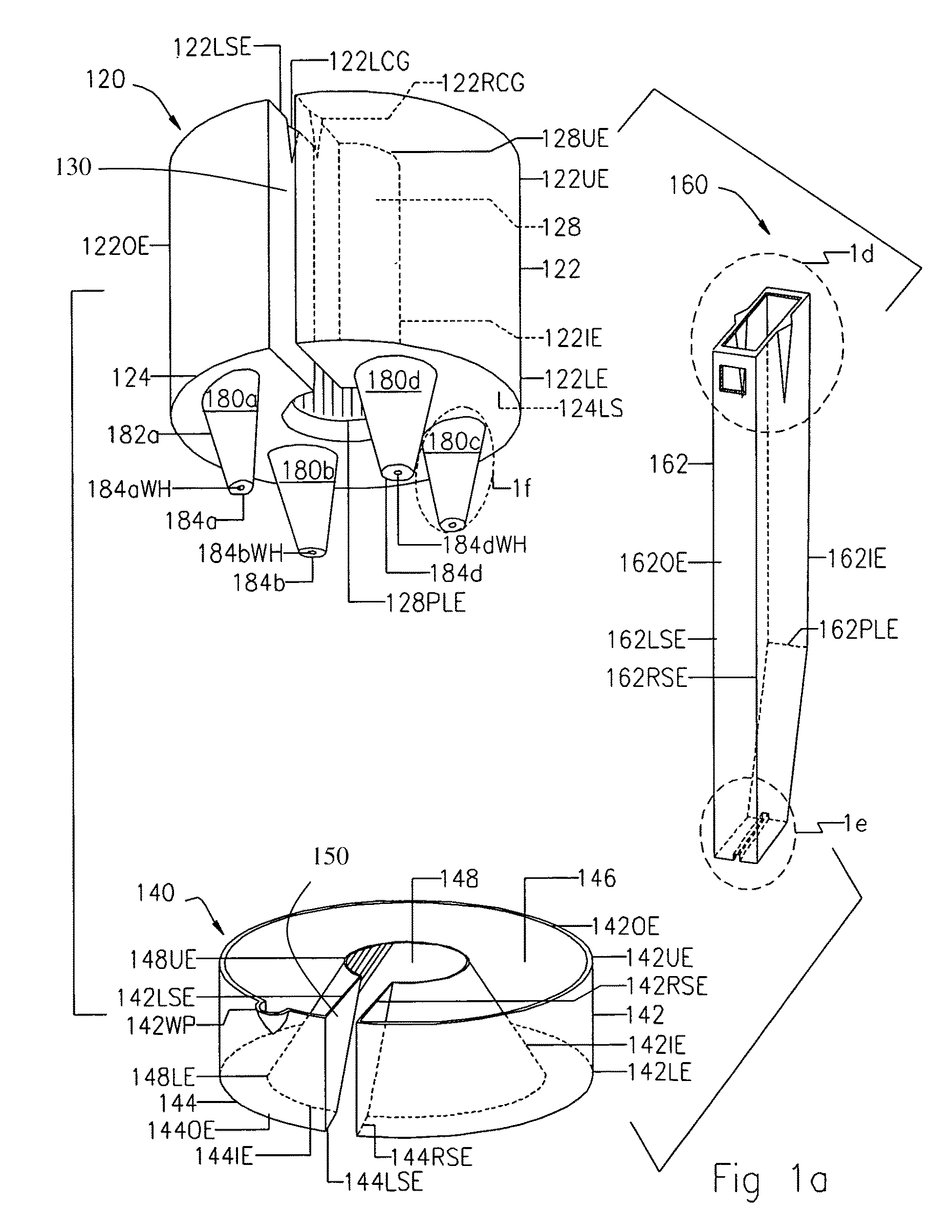
[0127]The alternate third embodiment includes an upper planter section 320 with a plurality of tetra-sectional circumferentially shaped circumferentially arrayed stands 380a, 380b, 380c, and 380d (bottom perspective view and top view) shown in FIGS. 3a and 3b, respectively, a lower reservoir section 140 (top perspective) shown in FIG. 1a, and a wedge section 160 (top perspective view) shown in FIG. 1a.

[0128]All aspects of the third embodiment are the same as the preferred embodiment except for the shape and configuration and array of a plurality of circumferentially arrayed stands 380a, 380b, 380c, and 380d being tetra-sectional circumferentially shaped instead of conical shaped. In all other aspects, the third embodiment is similar in structure as the preferred embodiment of the present invention.

fourth embodiment

Alternate Fourth Embodiment

FIGS. 4a-4c

[0129]The alternate fourth embodiment includes an upper planter section 420 and a lower reservoir section 440, both shown in top perspective view in FIG. 4a. FIGS. 4b and 4c show the alternate fourth embodiment in top view.

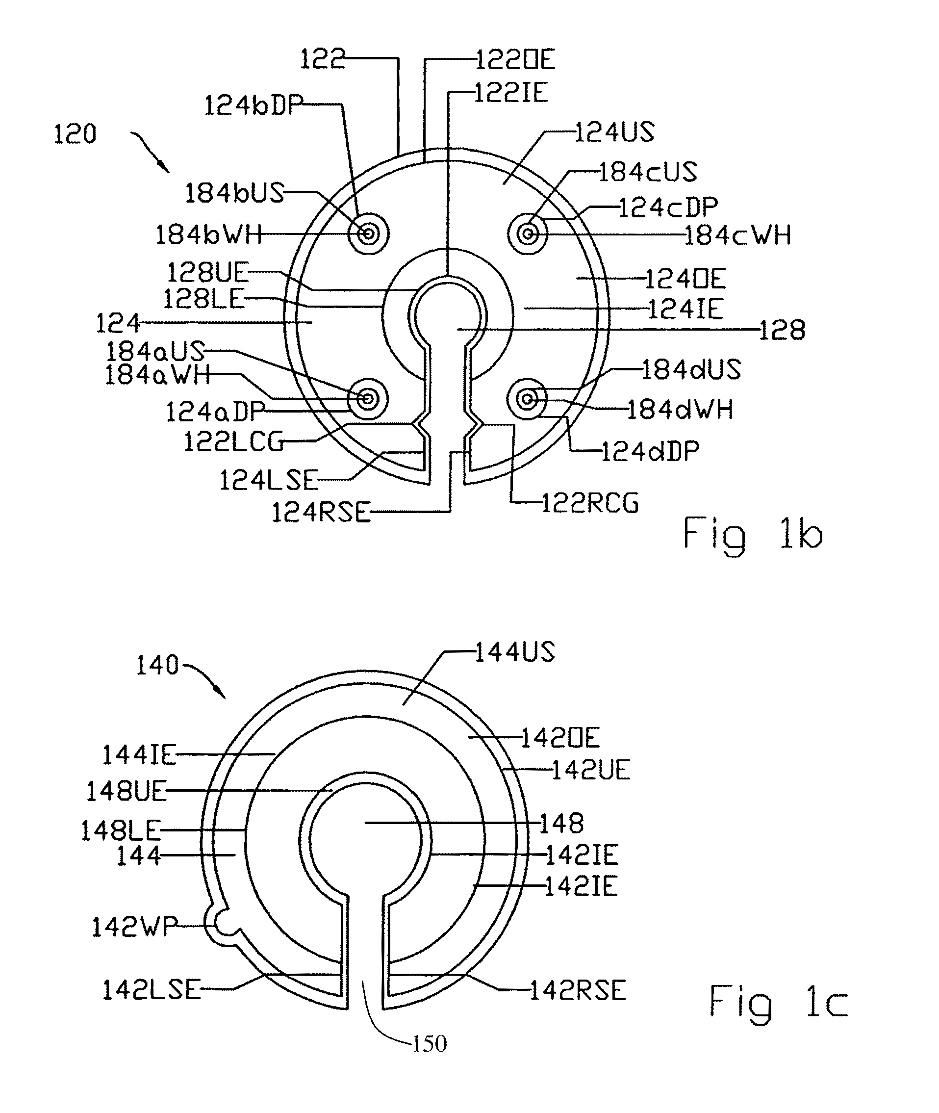
[0130]All aspects of the fourth embodiment are the same as the preferred embodiment except circumferentially arrayed stands 180a, 180b, 180c, and 180d of container 100 are excluded. Base panel 124 of upper planter section 420 is now a continuous surface with a plurality of longitudinal through-holes or drain ports 124aDP, 124bDP, 124cDP, and 124dDP.

[0131]In all other aspects, the fourth embodiment is similar in structure to the preferred embodiment of the present invention.

fifth embodiment

Alternate Fifth Embodiment

FIGS. 5a-5d

[0132]The alternate fifth embodiment includes a planter section 520 (top perspective view and top view) shown in FIGS. 5a and 5b, respectively, and a wedge section 160 (top perspective view) shown in FIG. 1a.

[0133]FIGS. 5a and 5b show an alternative design that combines upper planter section 120 and lower reservoir section 140 of the preferred embodiment to form a single planter section 520 of the alternate fifth embodiment.

[0134]FIG. 5a gives a good view of the fixture void 528 comprising of a pole void 528PV in the upper portion and a base void 528BV in the lower portion, as well as wedge void 130. As can be seen, said fixture void 528 connects to wedge void 130 that comprises an empty space in said container or said upper planter section capable of admitting the pole in said pole void (528PV), and capable of admitting the pedestal or base stand in said base void (528BV).

[0135]As further can be seen in FIG. 5a, the container wedge void 130 is...


PUM

PropertyMeasurementUnit
diameteraaaaaaaaaa
volumeaaaaaaaaaa
perimeteraaaaaaaaaa

Abstract

A container surrounding a pole and base stand of a freestanding floor lamp or similar device. The container includes a sidewall integrally attached to a base panel to form a ballast volume, a fixture void, and a wedge void extending into the ballast volume. The container can take on a variety of shapes and can be split into two sections comprising an upper planter section and a lower reservoir section. The upper planter section includes a ballast volume, a pole void and a wedge void and can include a plurality of drain ports with or without integrally attached circumferentially arrayed stands. The lower reservoir section includes a ballast volume, a wedge void, and a base void and can include a watering port. A wedge section can be provided to close off the wedge void and define the aperture in which a freestanding device such as a floor lamp is housed.

Description

CROSS-REFERENCE TO RELATED APPLICATIONS[0001]This application is a continuation in part of prior application Ser. No. 11 / 542,821, “Decorative pole and base stand stabilizing container”, filed Oct. 4, 2006, Maria N. Kamau inventor.BACKGROUND OF THE INVENTION[0002]1. Field of the Invention[0003]This invention relates to containers, specifically to plant receptacles used in combination with freestanding devices that have a pole and a base stand, such as a floor lamp.[0004]2. Background of the Invention[0005]Common freestanding fixtures such as floor lamps, floor fans, coat stands, hat stands, and patio sun umbrellas come equipped with a pole and a base stand. Often the base stands provided with such fixtures have at least one if not both of the following problems. Firstly, the base stands are too small or too lightweight to offer sufficient stability from accidental tip-over if bumped. Secondly, the base stands are often aesthetically incompatible with the home or office décor.[0006]Pr...

Claims


Application Information

Patent Timeline
Patent Type & Authority Patents(United States)
IPC IPC(8): A01G9/02
CPCA01G9/02A01G9/04E04H12/2246A01G27/02Y10T29/53
Inventor KAMAU, MARIA N
Owner KAMAU MARIA N
Learn More