
Seat structure for supporting an assembly from underneath

a seat structure and assembly technology, applied in the direction of ring springs, electrical apparatus casings/cabinets/drawers, furniture parts, etc., can solve the problems of prone to damage, difficulty in designing assembly in thin and compact size, etc., and achieve the effect of fine stability and minimal cost of material and construction

Inactive Publication Date: 2011-06-14
GEMTEK TECH CO LTD
View PDF5 Cites 8 Cited by
  • Summary
  • Abstract
  • Description
  • Claims
  • Application Information

AI Technical Summary

Benefits of technology

[0007]The object of the present invention is to provide a seat structure, which requires lesser material and manufacturing expense and which provides a fine stability to absorb vibration of an assembly equipped with the seat structure.
[0011]Since a certain part projecting from an outer casing of the assembly serves as the bottom seat and the flexible connecting elements of the seat structure of the present invention, the cost for material and construction is minimized in addition to providing a fine stability to absorb the vibration caused during operation of the assembly.

Problems solved by technology

Since the function of an electronic device increases, there should be ways to absorb vibration of the electronic device during the operation, since the vibration or inclined position of the device may affect the function ability thereof.
The above-stated resilient structure includes an upwardly curved portion, which occupies a relatively large space in the assembly, thereby causing difficulty to design the assembly in thin and compact size.
Moreover, in case the assembly encounters a relatively large impact, the resilient structure itself cannot absorb the impact, thereby tending to damage.

Method used


Image

  • Seat structure for supporting an assembly from underneath
  • Seat structure for supporting an assembly from underneath
  • Seat structure for supporting an assembly from underneath

Examples


Embodiment Construction

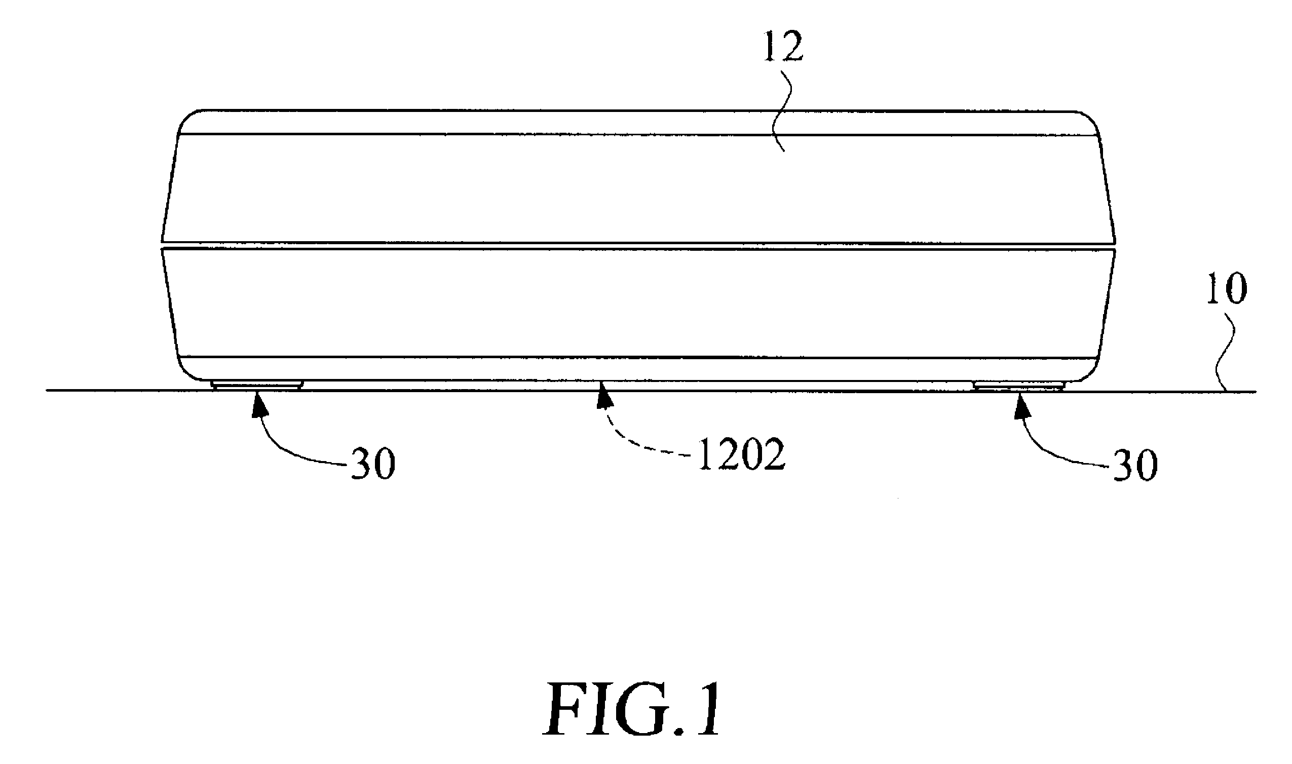
[0018]FIG. 1 is a perspective view of a seat structure 30 of the present invention for supporting an electronic assembly or device 12 from underneath. The seat structure 30 of the present invention is disposed below a base portion 1202 of the assembly 12 in order to absorb the vibration caused during operation of the assembly 12.

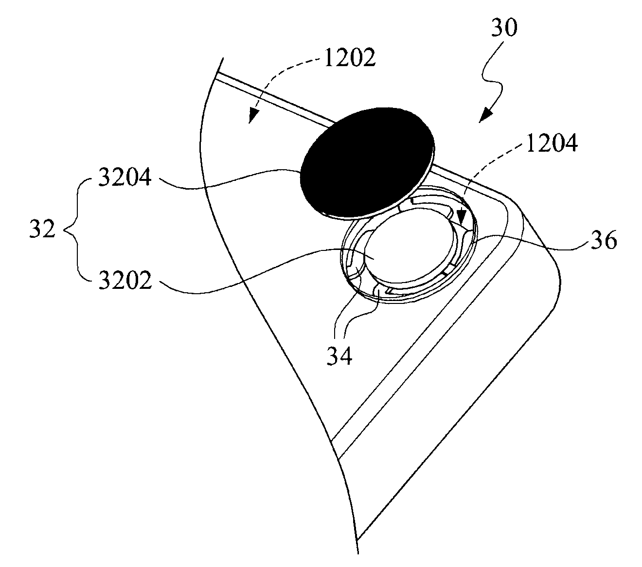
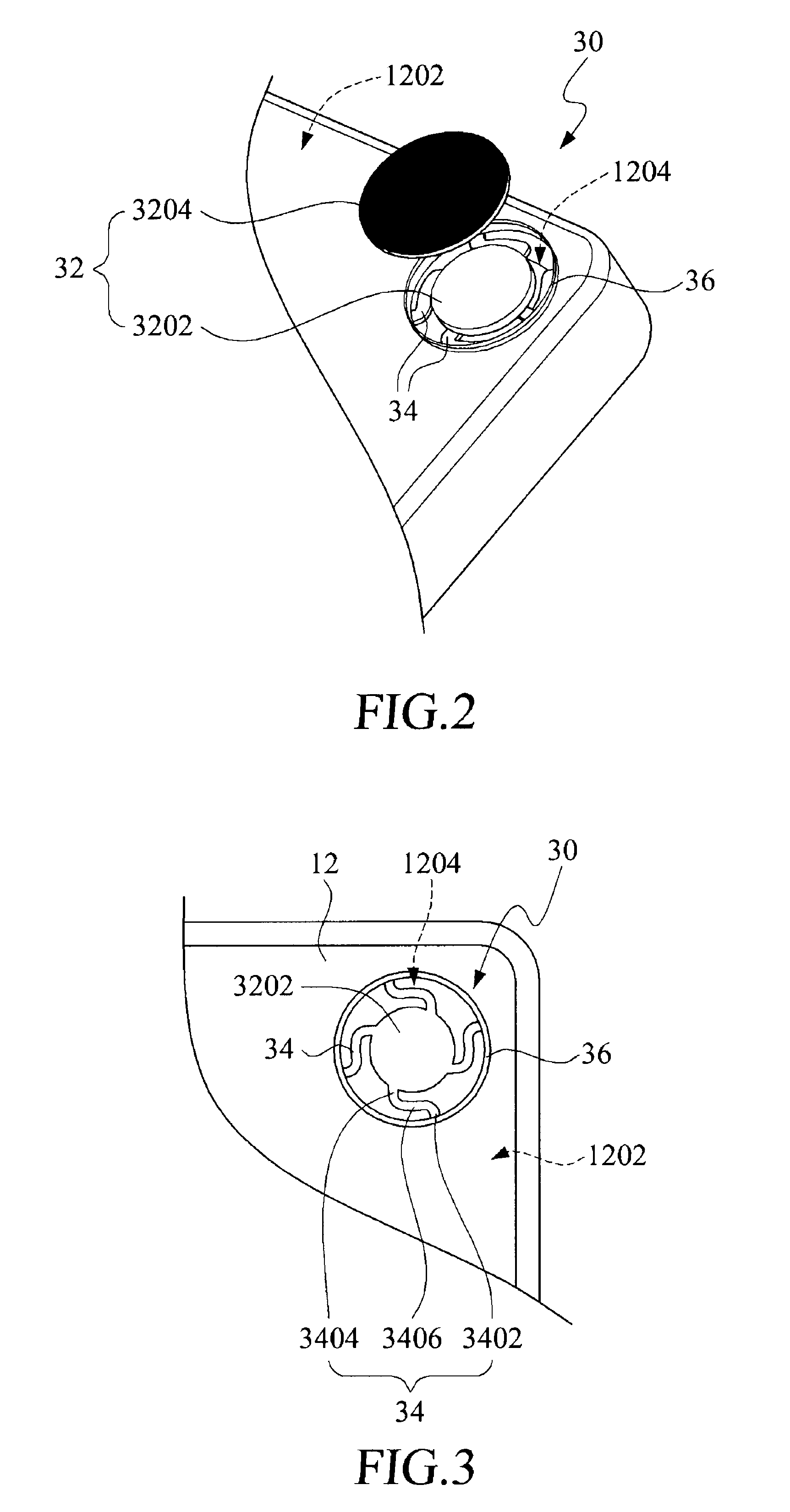
[0019]Referring to FIGS. 2 and 3, wherein FIG. 2 is an exploded view of the seat structure of the present invention, in which, the assembly 12 is turned upside down to illustrate attachment of the present seat structure 30 thereto. FIG. 3 is an enlarged view of a carrier disc and a bottom seat of the seat structure of the present invention. The base portion 1202 of the assembly 12 is formed with an opening 1204. In case the assembly 12 has four bottom corners, there should be four openings 1204 in the base portion 1202. Each seat structure 30 of the present invention includes a bottom seat 32 and a plurality of flexible connecting elements 34.

[0020]The botto...


PUM


Abstract

A seat structure is provided for disposing below an assembly in order to support the assembly from underneath. The assembly has a base portion formed with an opening. The seat structure includes a bottom seat for placing within the opening in the base portion and a plurality of flexible connecting elements. Each flexible connecting element includes an outer bent end connected to a periphery confining the opening in the base portion, an inner bent end connected to the bottom seat and a main body between the outer and inner bent ends. The vibration of the assembly is absorbed by the seat structure to provide stability to the assembly.

Description

FIELD OF THE INVENTION[0001]The present invention relates to a seat structure, and more particularly to a seat structure for disposing below an electronic device or assembly so as to support the same from underneath and to absorb the vibration caused due to operation of the electronic device.BACKGROUND OF THE INVENTION[0002]Since the function of an electronic device increases, there should be ways to absorb vibration of the electronic device during the operation, since the vibration or inclined position of the device may affect the function ability thereof.[0003]A seat structure is generally implemented in order to eliminate the aforementioned disadvantage. The seat structure can be an independent element or is coupled to the bottom of the assembly via a fastener bolt. It happens that the manufacturers of the assembly and the seat structure have no communication with each other so that the seat structure's manufacturer considers the structure design only in view of the available mat...

Claims


Application Information

Patent Timeline
Patent Type & Authority Patents(United States)
IPC IPC(8): F16M11/20
CPCA47B91/005H05K5/0234F16F15/04F16F1/027
Inventor CHIU, HSIEN-CHIH
Owner GEMTEK TECH CO LTD
Learn More