Lamp housing for high-power LED street lamp

a technology of led street lamps and housings, which is applied in the direction of lighting support devices, lighting and heating apparatuses, light source combinations, etc., can solve the problems of non-uniform brightness in the illumination field, light shape, and distribution design of matrix, and achieve the effect of improving illumination brightness and maximising effective illumination area

Inactive Publication Date: 2011-06-14
GENIUS ELECTRONICS OPTICAL CO LTD
View PDF21 Cites 110 Cited by
  • Summary
  • Abstract
  • Description
  • Claims
  • Application Information

AI Technical Summary

Benefits of technology

[0011]The purpose of this invention is to provide a lamp housing for a high-power LED street lamp to install LED lamp arrays to generate the optimum light distribution, so as to substantially increase the range of the effective illumination field, and improve the brightness of the effective illumination field and the light emitting uniformity of the effective illumination field.
[0013]Accordingly, after installing a LED lamp array module on the rectangular planes, the maximum effective illumination area can be produced from the LED lamp array modules through the two outermost rectangular planes. Further, by incorporating with mutually different vertical direction of the plurality of rectangular planes between the middle positions, the light beams emitted from each installed LED lamp array module can be overlapped and projected to the foregoing effective illumination field with respect to different interlaced optical angles to provide uniform distribution for the projection angle and improve the illumination brightness.

Problems solved by technology

However, it is doubted that whether the light distribution design of the matrix provided for installing the LED light source modules, such as several load planes corresponding to the matrix and several load planes corresponding to each other, can achieve the optimum light distribution.
Consequently, the included angles of adjacent load planes are too big that easily causes fewer field interlaced due to the light emitting direction of the LED light source modules installed on each load plane, resulting in light shape problem and non-uniform brightness in the illumination field.
Consequently, in the effective illumination field, the brilliance of the middle illumination field is too strong, and the outer illumination field may have halation.

Method used


Image

  • Lamp housing for high-power LED street lamp
  • Lamp housing for high-power LED street lamp
  • Lamp housing for high-power LED street lamp

Examples


Embodiment Construction

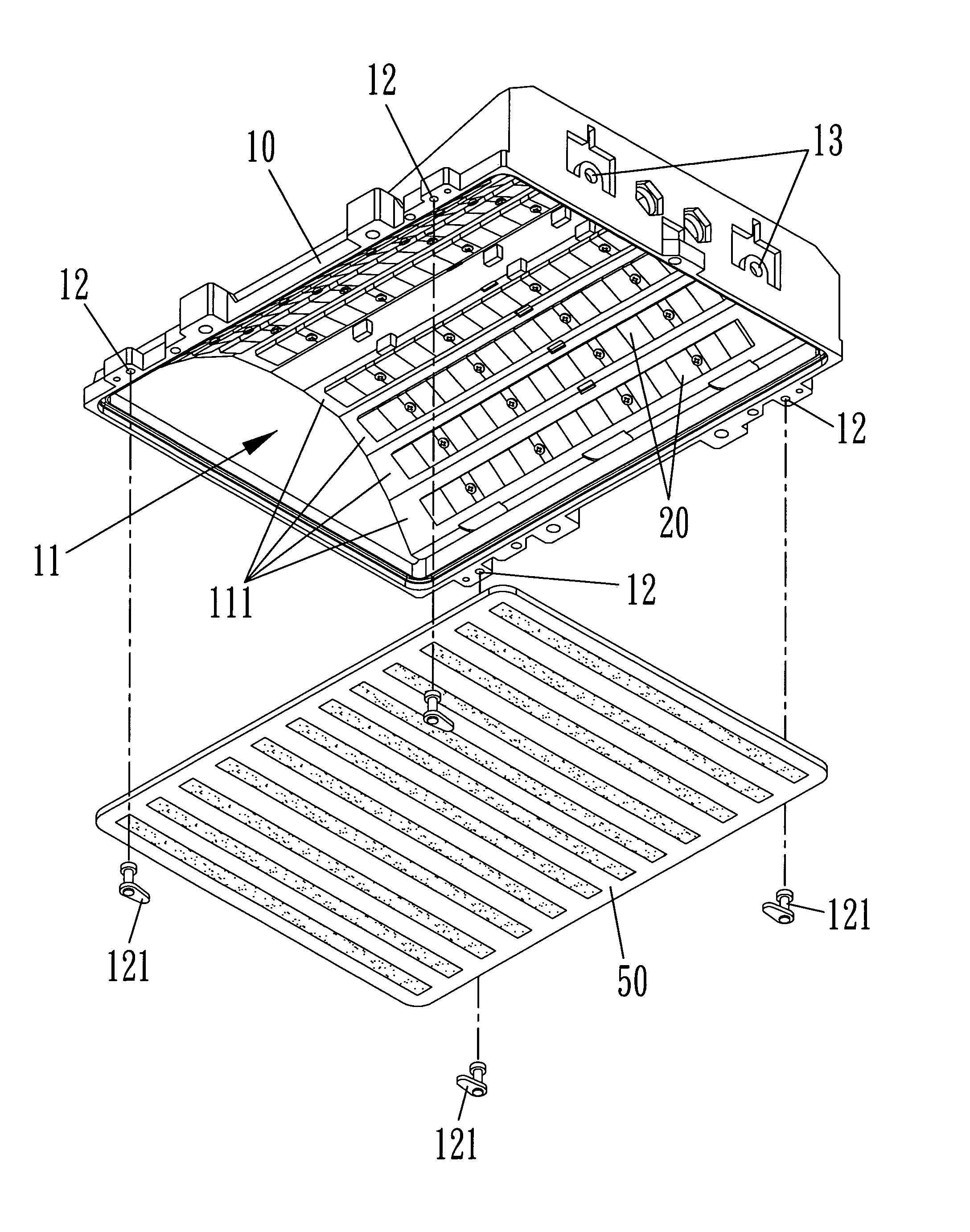
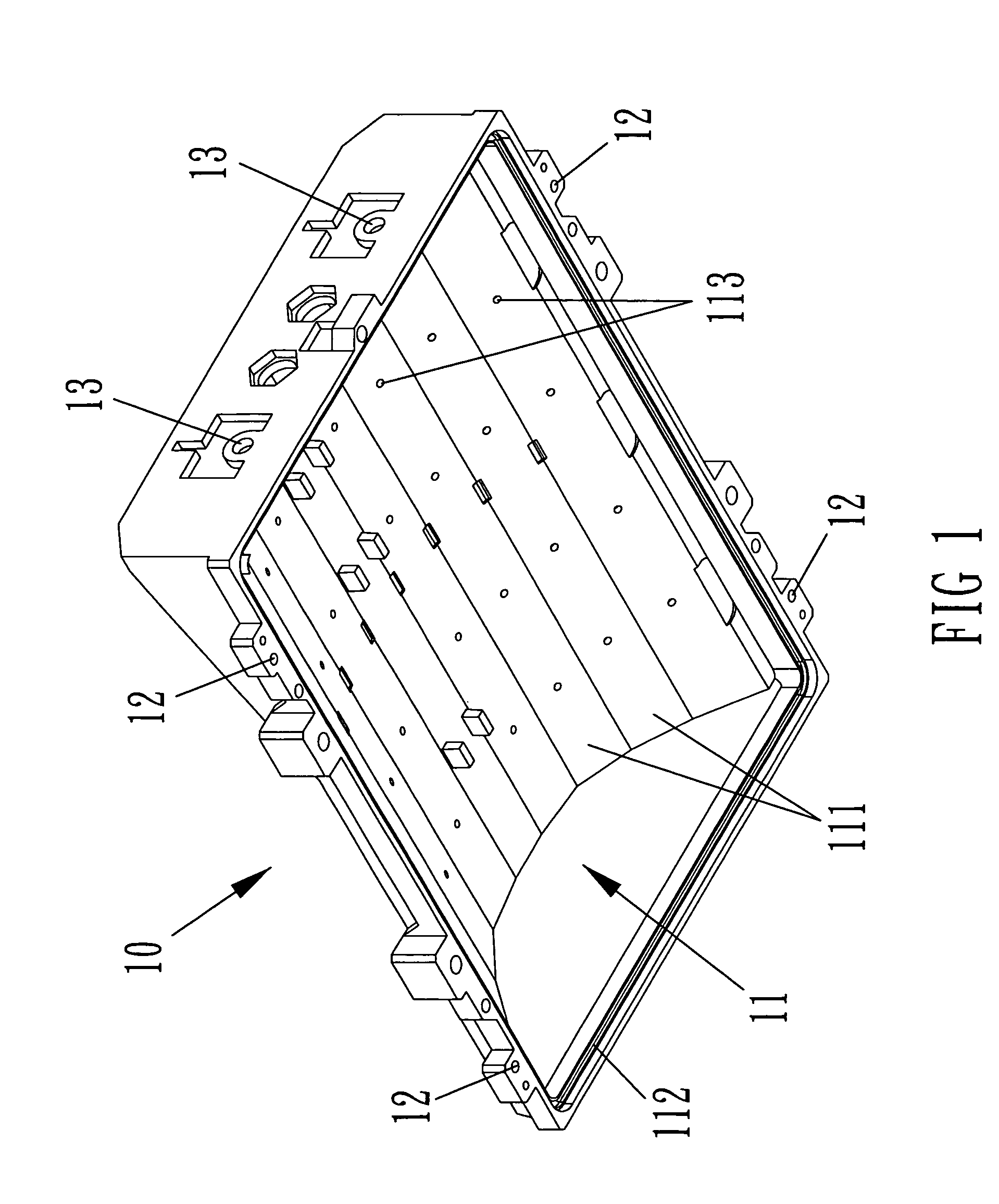
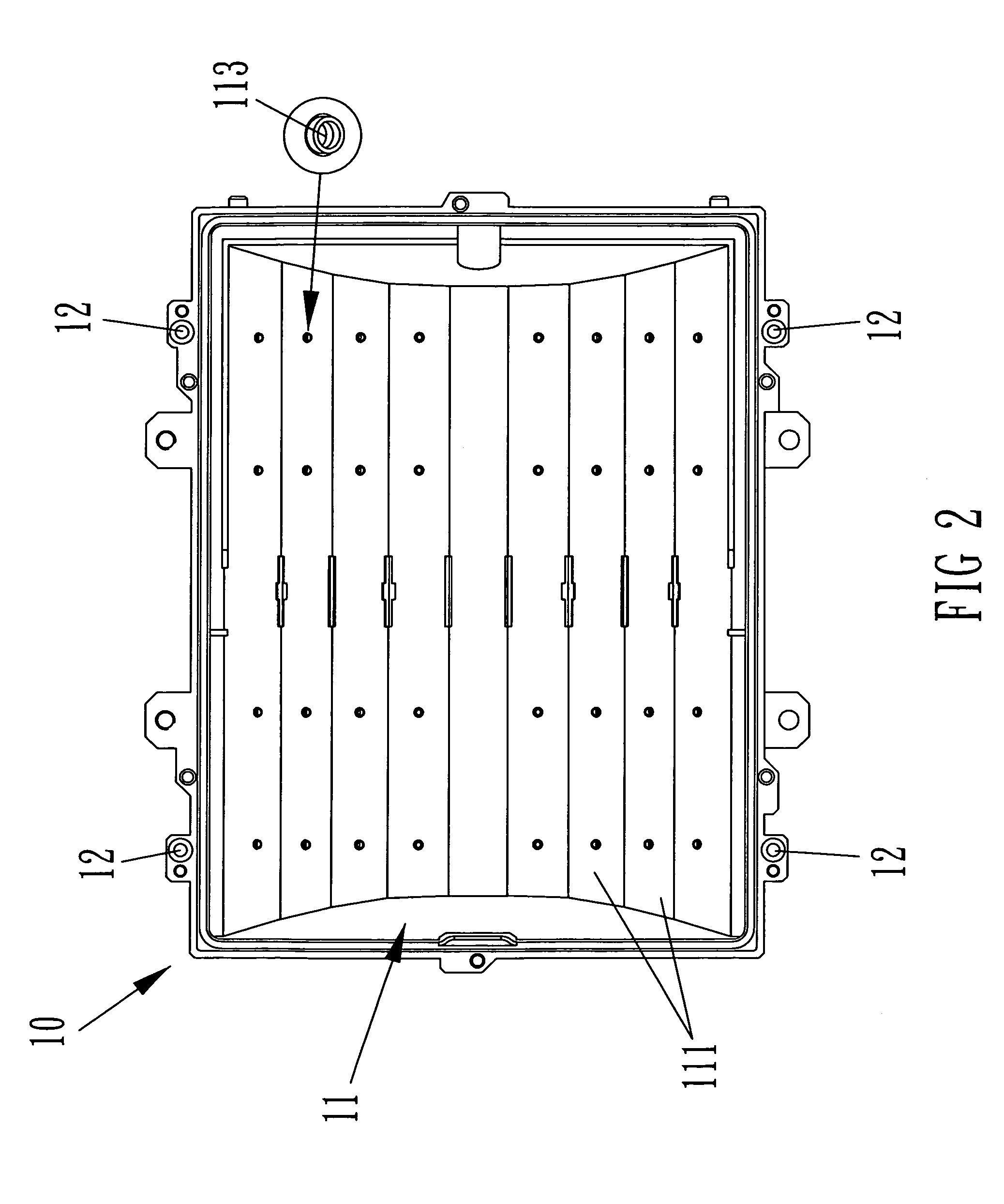
[0027]Referring to FIGS. 1-3, a lamp housing 10 for a high power LED street lamp of the present invention is shown. The lamp housing 10 comprises a back wall and a plurality of side walls cooperating with the back wall to define an open bottom end and a polygonal chamber 11 for installing a plurality of LED lamp array modules 20 (as shown in FIGS. 4-6). The polygonal chamber has at least four rectangular planes 111 formed symmetrically at each side of centerline of the back wall 11. Each rectangular plane 111 is disposed on each side progressively farther from the centerline and parallel to one another.

[0028]A rim groove 112 is formed at a bottom inner edge of the polygonal chamber 11 for embedding a rubber gasket (not shown in the figures) so that after sealing a lamp cover 50 (as shown in FIGS. 7 and 8) on the bottom inner edge, the rubber gasket can be closely in contact with the rim groove 112 through the lamp cover 50. The inside of the polygonal chamber 11 can be isolated from...


PUM


Abstract

A lamp housing for a high-power LED street lamp has symmetrical rectangular planes formed at each side of a centerline of a back wall thereof. The included angle intersected with direction lines normal to the two outermost symmetrically rectangular planes is between 60˜140 degrees. The rectangular planes are adapted for containing high-power LED modules to emit light with various interlacing included angles and at interlacing locations.

Description

FIELD ON THE INVENTION[0001]The present invention relates to a lamp housing for a high power LED (light emitting diode) street lamp, which is capable of installing multiple LED light source modules to produce a greater and more effective illumination field, to enhance the illumination intensity and uniformity in the effective illumination field, and to increase optical angles with high brightness.BACKGROUND OF THE INVENTION[0002]In recent years, since the brightness of LEDs is continuously developed and improved, the application scope of LEDs is greatly expanded. The grouped LEDs are sufficient to produce an illumination efficiency with great power by incorporating an array technique with the optical angle design.[0003]For example, a conventional large power LED street lamp is disclosed in a China patent application number, 200710043662.7, which includes LED light source modules installed on a matrix set in the large power LED street lamp adjacently protruding upwards to the light e...

Claims


Application Information

Patent Timeline
Patent Type & Authority Patents(United States)
IPC IPC(8): F21V29/00F21V21/116
CPCF21V15/01F21V29/004F21V29/717F21V29/2212F21S2/005F21V19/001F21W2131/103F21Y2101/02Y02B20/72F21Y2113/00F21Y2115/10F21V29/71F21V29/74
Inventor HO, YEN-WEI
Owner GENIUS ELECTRONICS OPTICAL CO LTD
Why Eureka
Try Eureka