Air conditioning system with electrostatically atomizing function

an air conditioning system and function technology, applied in air humidification systems, lighting and heating apparatuses, heating types, etc., can solve the problems of electrostatically atomizing units that are not able to generate electrostatically atomizing units are not able to condense the water from the conditioned air, and extremely lessen the mist of charged minute water particles

Inactive Publication Date: 2011-06-14
MATSUSHITA ELECTRIC WORKS LTD
View PDF35 Cites 16 Cited by
  • Summary
  • Abstract
  • Description
  • Claims
  • Application Information

AI Technical Summary

Benefits of technology

[0005]In view of the above problem, the present invention has been achieved to provide an air conditioning system with the electrostatically atomizing function for effectively spreading the mist which is generated by the electrostatically atomizing to the space.
[0006]The air conditioning system in accordance with the present invention comprises an electrostatically atomizing unit and a ventilation duct configured to flow a conditioned air and to have an air outlet for sending the conditioned air. The electrostatically atomizing unit comprises an emitter electrode, a water supplying means for supplying water to the emitter electrode, an opposed electrode disposed in an opposed relation to the emitter electrode, and a high voltage source. The high voltage source is configured to apply a high voltage across the emitter electrode and the opposed electrode, thereby electrostatically atomizing the water at a tip of the emitter electrode to generate a mist of charged minute water particles flowing from the emitter electrode towards and through the opposed electrode. The electrostatically atomizing unit comprises a discharge port for discharging the mist of the charged minute water particle. The electrostatically atomizing unit is disposed outwardly of the ventilation duct to locate the discharge port adjacent to the air outlet in order to carry the mist on the conditioned air flowing from the air outlet. In this case, the air conditioning system is able to spread the mist of the charged minute water particles extensively and effectively to the interior space without causing the dissipation of the mist of the charged minute water particles at the ventilation duct.
[0009]Preferably, the extension duct is a bendable flexible duct. In this case, the bendable flexible duct increases a degree of a freedom of an arranging position of the electrostatically atomizing unit.
[0010]Preferably, the extension duct is tapered to have its inside diameter smaller towards the discharge port than at the connection with the atomization barrel. The electrostatically atomizing unit generates noise by applying the high voltage for generating the mist of the charged minute water particles. In this case, the extension duct is able to reduce the noise leakage to the outside. Consequently, the extension duct is able to provide the noise reduction effect.
[0012]In addition, it is preferable that the ventilation duct is configured to have a branch duct which merges to a portion of the extension duct to flow a portion of the conditioned air into the extension duct. In this case, the conditioned air creates airflow inside the extension duct. The airflow effectively carries the mist of the charged minute water particles to the air which is discharged from the air outlet effectively.

Problems solved by technology

But in the case to incorporate the electrostatically atomizing unit into the air conditioning system, a following problem occurs.
But, the above electrostatically atomizing unit is not able to condense the water from the conditioned air.
As a result, the above electrostatically atomizing unit is not able to generate the mist of the charged minute water particles.
In this way, the ventilation duct causes the problem to extremely lessen an amount of the mist of the charged minute water particles for discharging to the interior space of the automobile.

Method used


Image

  • Air conditioning system with electrostatically atomizing function
  • Air conditioning system with electrostatically atomizing function
  • Air conditioning system with electrostatically atomizing function

Examples


Embodiment Construction

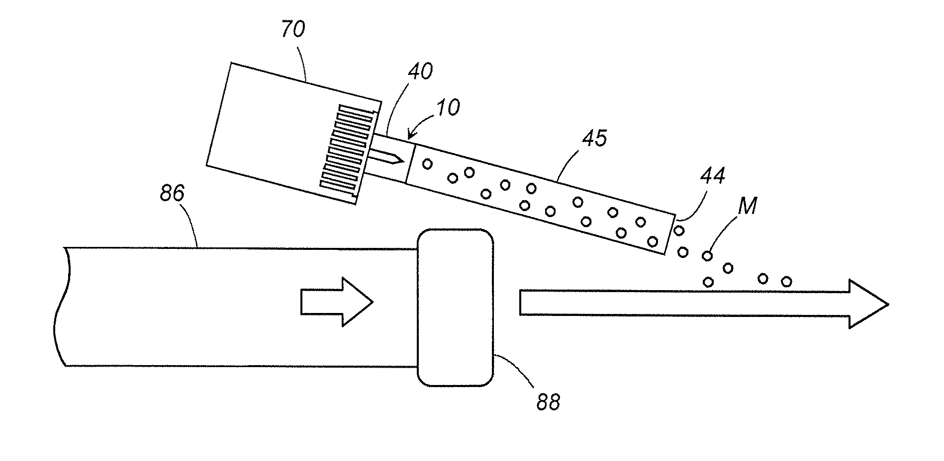
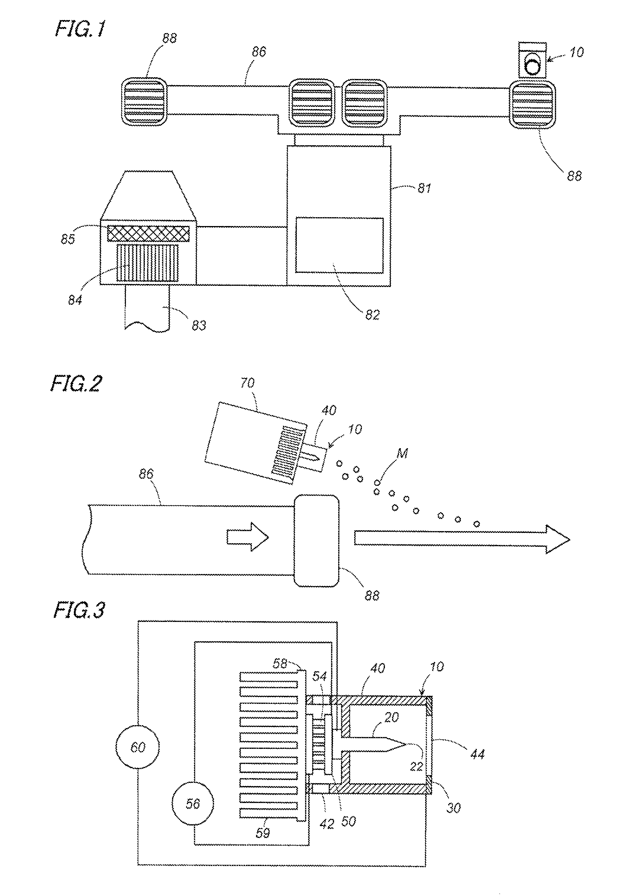
[0020]Now, a reference is made to the attached drawings to explain an air conditioning system in accordance with an embodiment of a present invention. FIG. 1 shows an example of the present invention which is incorporated to the air conditioning system for automobile use. The air conditioning system includes a heat exchanging chamber 81, an air incoming duct 83, and a ventilation duct 86. The heat exchanging chamber 81 includes a heat exchanger 82. The air incoming duct 83 is provided in order to take the air of the inside and outside of the automobile to the heat exchanger 81. The ventilation duct 86 is provided in order to send the air which is heat-exchanged at the heat exchanging chamber 81 to the inside of an automobile. The air incoming duct 83 is provided with a fan 84 for taking the air, and an air filter 85. The fan 84 creates a forced airflow. The forced airflow sends conditioned air to the inside of the automobile from air outlets 88 which are disposed at the front end of...


PUM


Abstract

An air conditioning system with an electrostatically atomizing function includes an electrostatically atomizing unit and a ventilation duct which flows conditioned air. The electrostatically atomizing unit generates a mist of charged minute water particles. The electrostatically atomizing unit is provided with a discharge port which locates adjacent to an air outlet of the ventilation duct. The mist of the charged minute water particles flows into an airflow which is sent from the ventilation duct. The mist of the charged minute water particles effectively spreads to the space by the air flow without dissipating inside the ventilation duct.

Description

TECHNICAL FIELD[0001]The present invention relates to an air conditioning system with an electrostatically atomizing function generating a mist of charged minute water particles.BACKGROUND ART[0002]Japanese patent application no. 2005-131549A discloses an electrostatically atomizing unit which generates the mist of the charged minute water particles by electrostatically atomizing water. The electrostatically atomizing unit atomizes the water which is supplied to an emitter electrode by Rayleigh breakup so as to generate the mist of the charged minute water particles of nanometer size. The mist of the charged minute water particles includes radicals, is able to float in air over an extended time period, and is able to spread in the air in large quantity. The mist of the charged minute water particles adheres to malodorous component which adheres to surface of walls, clothes, and curtains of the space where the mist is discharged, and subsequently deodorizes the malodorous component e...

Claims


Application Information

Patent Timeline
Patent Type & Authority Patents(United States)
IPC IPC(8): B03C3/16
CPCB05B5/0255B05B5/057F24F6/12B60H3/022B60H3/0071B60H3/024
Inventor YANO, TAKESHIHIRAI, TOSHIHISAHIRAI, LEGAL REPRESENTATIVE, KISHIKOWADA, SUMIOSUGAWA, AKIHIDEMATSUMOTO, TATSUHIKOAKISADA, SHOUSUKE
Owner MATSUSHITA ELECTRIC WORKS LTD
Why Eureka
Try Eureka