Method and apparatus for monitoring latency, jitter, packet throughput and packet loss ratio between two points on a network

a technology of packet throughput and packet loss ratio, applied in data switching networks, instruments, frequency-division multiplexes, etc., can solve the problem of reducing the available bandwidth of individuals communicating over the segment, testing cannot be sure that it is reporting conditions, and it is virtually impossible to predict the route of packets through the network

Inactive Publication Date: 2011-06-14
SPIRENT COMM
View PDF9 Cites 122 Cited by
  • Summary
  • Abstract
  • Description
  • Claims
  • Application Information

AI Technical Summary

Problems solved by technology

A drawback to the above-described technique is that data must be injected into the segment bandwidth that is used by the public, possibly reducing available bandwidth that individuals communicating over the segment being tested share.
Another problem may occur over network segments that are enhanced for multiprotocol label switching (MPLS), an Internet Engineering Task Force (IETF) initiative that provides alternate routing paths.
Otherwise, the test can not be sure that it is reporting the conditions that a customer is experiencing because the signal data packets may not travel the same paths or be queued in the same router queues as the customer stream.
With the use of MPLS and other dynamic routing methods then, it is virtually impossible to predict the route of a packet through the network and any injected packet is unlikely to follow the same route in a complex load balanced network.

Method used


Image

  • Method and apparatus for monitoring latency, jitter, packet throughput and packet loss ratio between two points on a network
  • Method and apparatus for monitoring latency, jitter, packet throughput and packet loss ratio between two points on a network
  • Method and apparatus for monitoring latency, jitter, packet throughput and packet loss ratio between two points on a network

Examples


Embodiment Construction

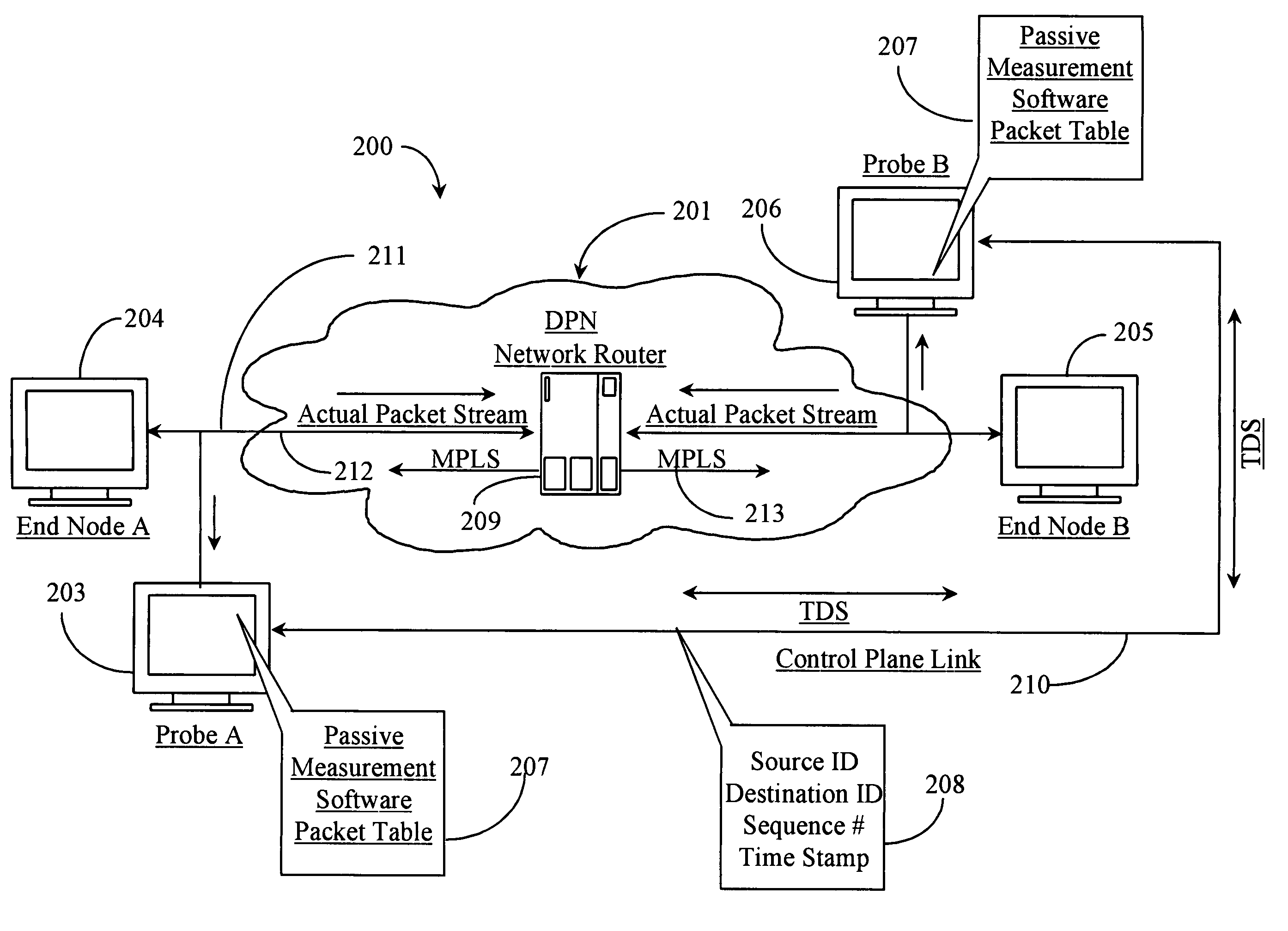
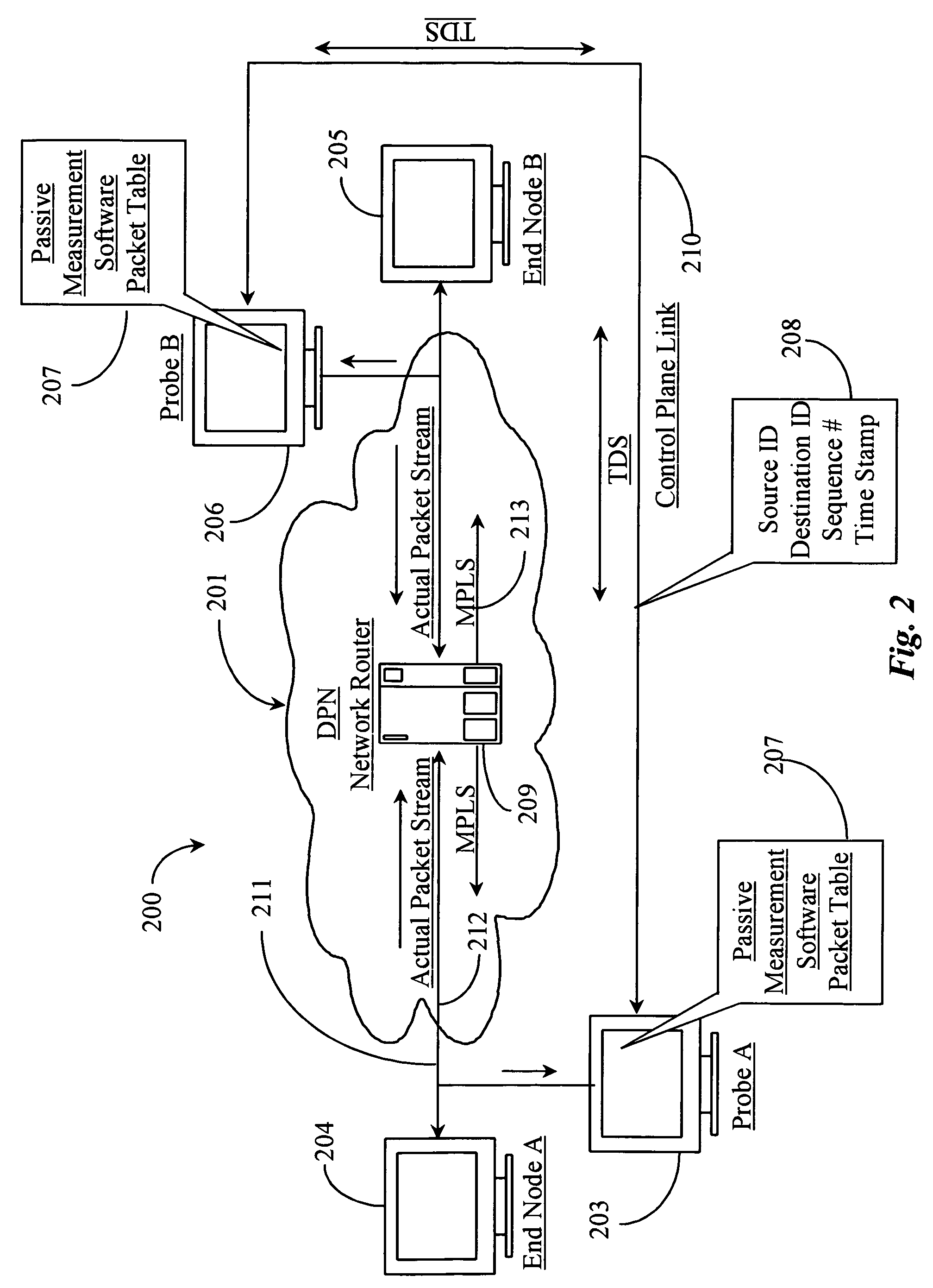
[0029]According to an embodiment of the present invention, the inventor provides a method and apparatus for passively testing a network segment of a DPN for performance data. The method and apparatus of the invention will be described in detail in the following embodiments.

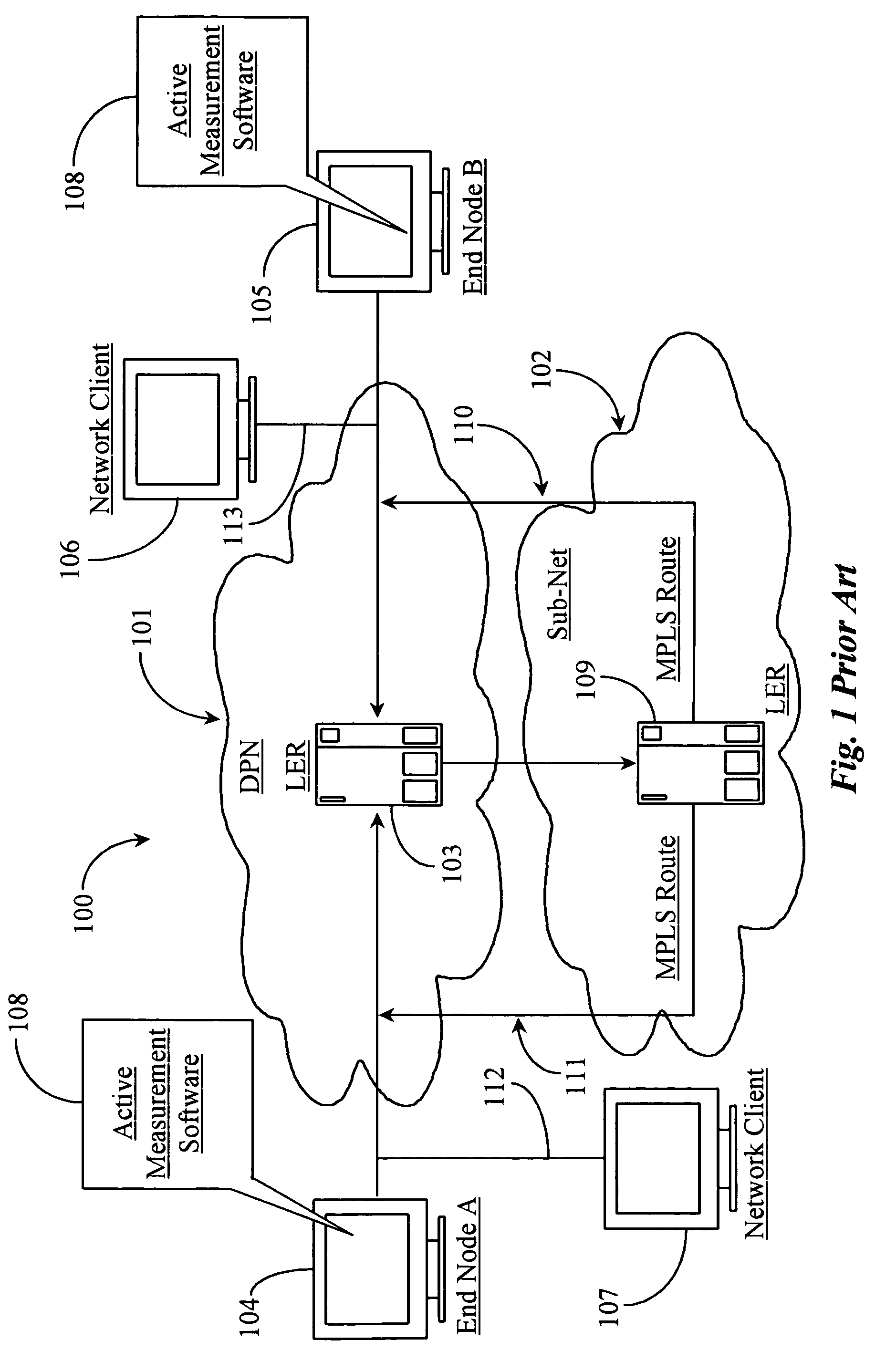
[0030]FIG. 1 is a logical architectural overview 100 of a network segment tested for performance according to prior art. Architecture 100 includes, in this example, a data-packet-network (DPN) 101 and a sub-net 102. DPN 101 may represent a portion or segment of an Ethernet network, an IP network such as an Internet or Intranet, a private wide-area-network (WAN), or a local-area-network (LAN).

[0031]Network 101 has a segment or routing path illustrated therein that serves to connect two end nodes, an end node 104 and an end node 105, also referred to herein as end nodes A and B respectively and as labeled. End nodes A and B represent communicating nodes that may communicate with one another over the illustrated path...


PUM


Abstract

A system for testing a segment of a data-packet-network has a first probe connected substantially at one end of the segment; a second probe connected substantially at the opposite end of the segment from the location of the first probe; and a process application distributed to each probe. The first and second probes collect data from and time stamp data packets as they pass forming first and second records of the individual packets whereupon the second-formed records of each packet are compared with the first records of each packet for record matching, time-stamp comparison and test result processing.

Description

FIELD OF THE INVENTION[0001]The present invention is in the field of data-packet-network (DPN) performance testing and pertains particularly to a method and apparatus for passive measurement of packet latency from one point to another point and subsequent calculation of packet loss ratio for a network line or segment.BACKGROUND OF THE INVENTION[0002]In the field of performance testing for data-packet-networks (DPNs), administrators attempt to gauge performance characteristics of various network segments and lines in real time in order to better manage network traffic. In most applications there are four basic measurements whose results provide various pieces of information regarding some aspect of performance. These four basic measurements are:[0003]Latency-defined as the average time it takes a data packet to travel from one point on a DPN to another point on the DPN.[0004]Jitter-defined as variation in latency measured between two endpointson a DPN over a given time frame.[0005]Pa...

Claims


Application Information

Patent Timeline
Patent Type & Authority Patents(United States)
IPC IPC(8): H04L1/00H04J1/16H04J3/14H04L1/20H04L1/24H04L12/26H04L12/28
CPCH04L1/205H04L1/24H04L43/0852H04L43/106H04L43/0829H04L43/12
Inventor MCBEATH, TOM
Owner SPIRENT COMM
Why Eureka
Try Eureka