Cuff closures for dress shirts

a technology for dress shirts and cuffs, applied in the direction of cuffs, clothing, applications, etc., can solve the problem that the cuff links cannot be used with these traditional dress shirts

Inactive Publication Date: 2011-06-21
BLAKELY JOHN FORD
View PDF15 Cites 12 Cited by
  • Summary
  • Abstract
  • Description
  • Claims
  • Application Information

AI Technical Summary

Benefits of technology

[0012]These and other objects, features, and/or advantages may accrue from various

Problems solved by technology

Consequently, cuff links cannot be used with these traditional standard dress shirts.
Few apparel enhancements

Method used


Image

  • Cuff closures for dress shirts
  • Cuff closures for dress shirts
  • Cuff closures for dress shirts

Examples


Embodiment Construction

[0031]Particular embodiments of the present invention will now be described in greater detail with reference to the figures.

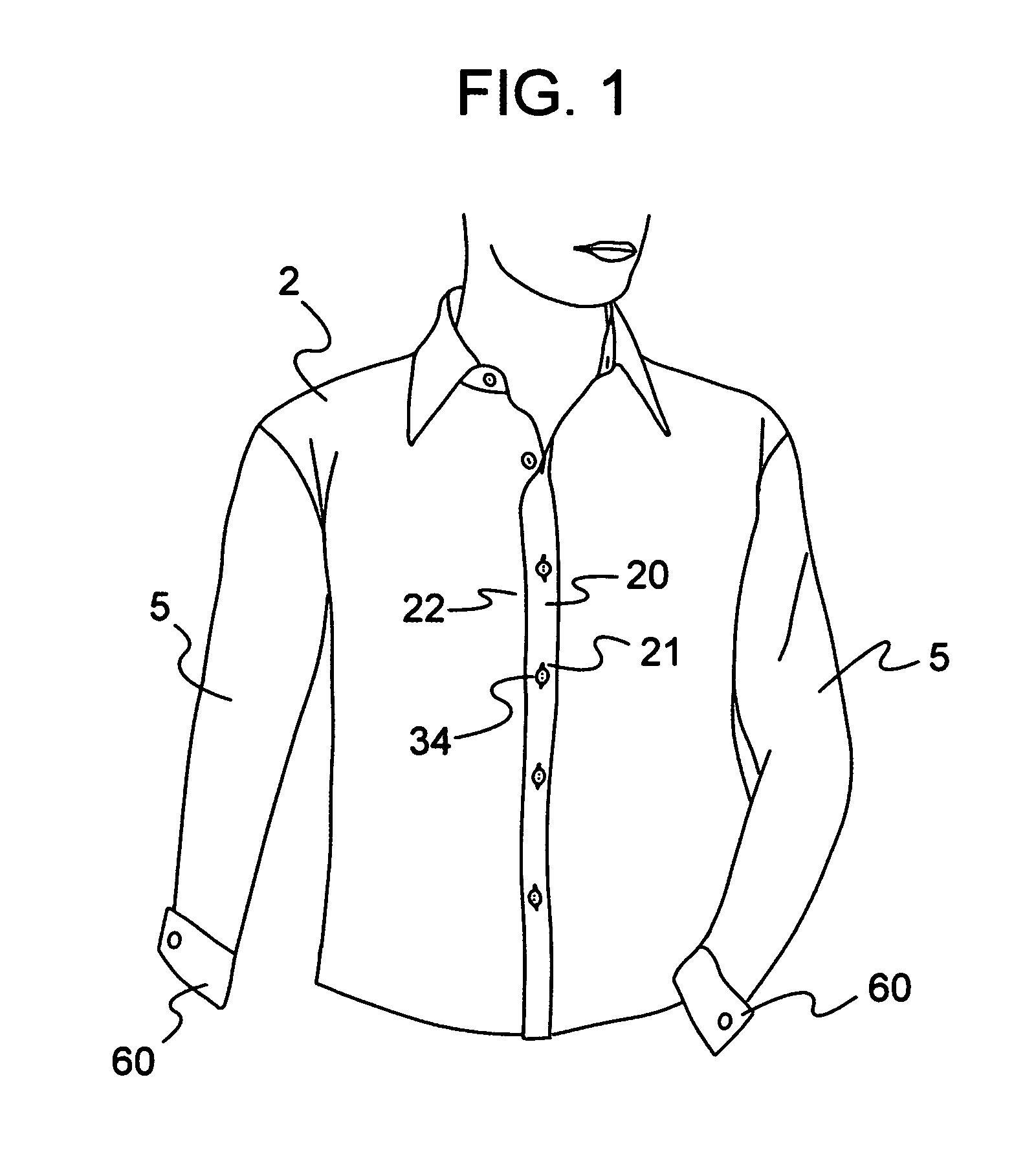
[0032]FIG. 1 is an exemplary illustration of a traditional dress shirt 2. As shown, the dress shirt 2 includes a front shirt panel 20 and a rear shirt panel 22. The front shirt panel 20 is shown attached to the rear shirt panel 22 with a plurality of fasteners 34 and associated eyelet holes 21 adapted to receive the various fasteners. The various fasteners secure the dress shirt 2 to the torso of the user. The dress shirt 2 also includes a pair of shirt cuffs 60 attached to a pair of shirt sleeves 5.

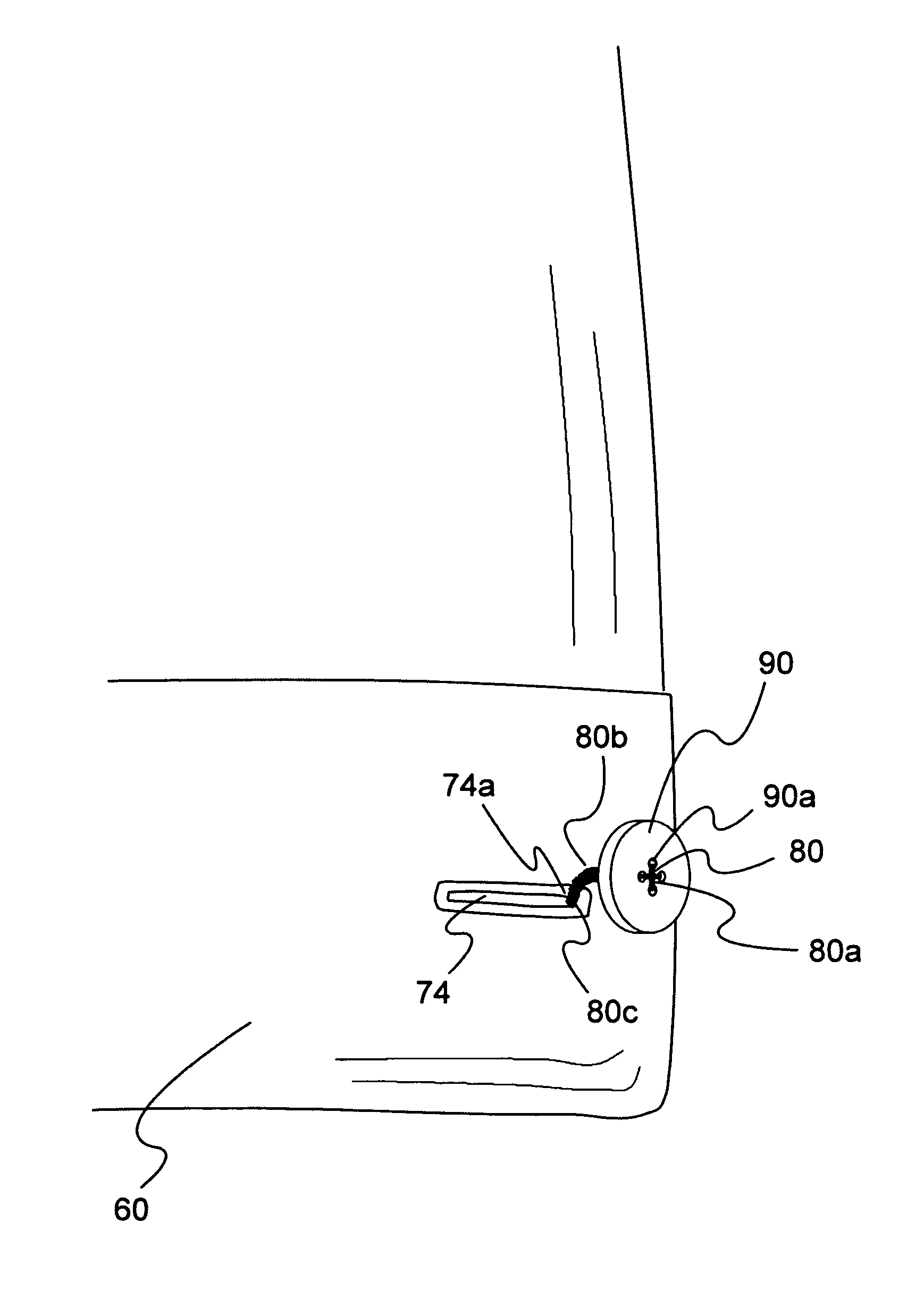
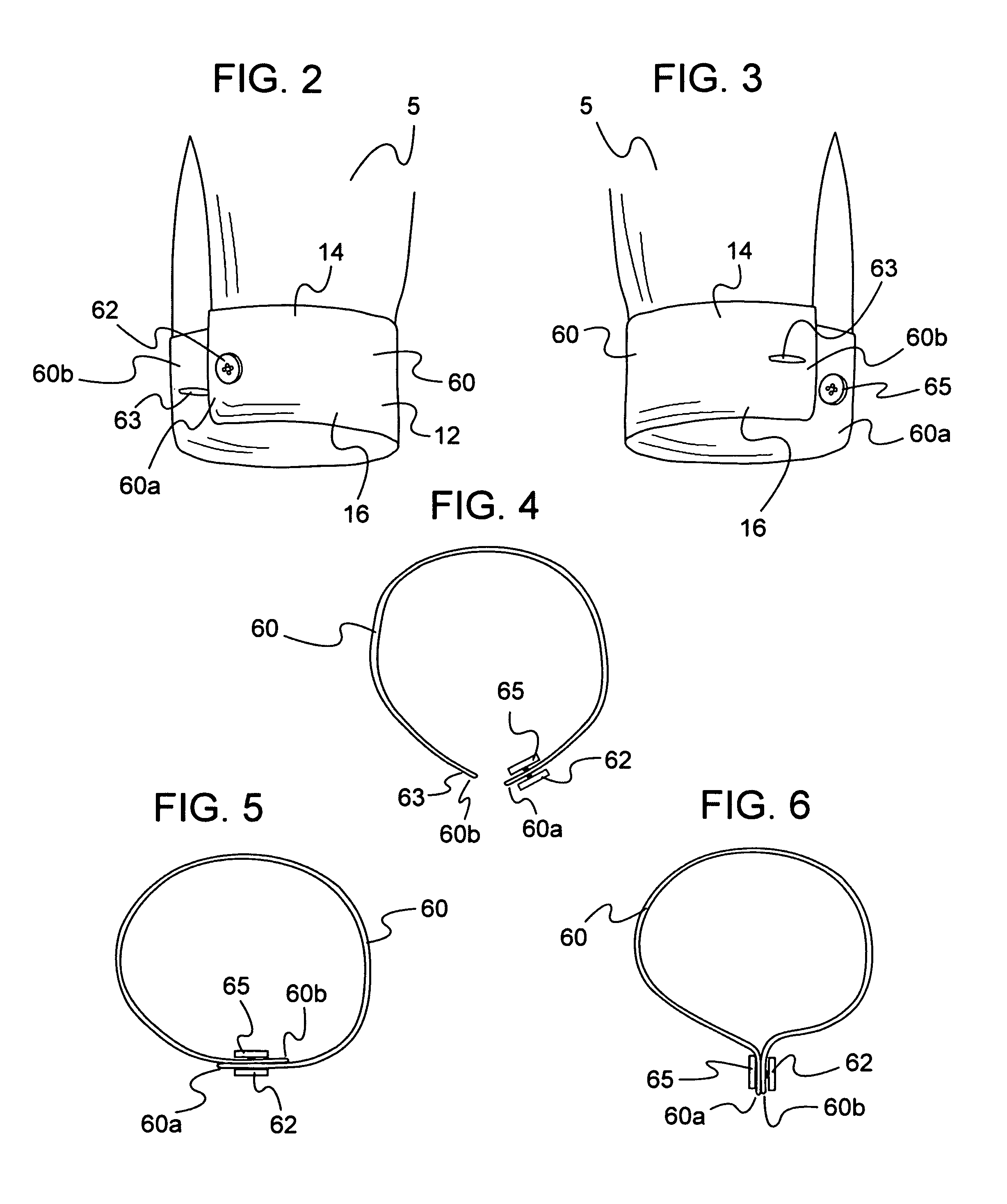
[0033]The shirt cuff 60 includes a band of material 12 having a first edge 14 and an opposing second edge 16. The first edge 14 is attached to the sleeve 5 of the shirt 2. Each of the shirt cuffs 60 includes a first cuff end 60a and a second cuff end 60b.

[0034]FIG. 2 is an exemplary illustration of the dress shirt sleeve 5 attached to the dress shirt cuff 60. As sh...


PUM


Abstract

A shirt cuff for a long-sleeved garment including a band of material having first and second opposing edges and first and second opposing cuff ends, wherein the first edge is attached to the sleeve of the shirt. A closure device is comprised of a hidden button and first eyelet combination, respectively disposed separately at the first and second opposing ends. A button-side eyelet may also be disposed adjacent to the hidden button on the first cuff end, and a cuff-link may be placed through the first eyelet and the button-side eyelet to form a French cuff configuration.

Description

BACKGROUND OF THE INVENTION[0001]1. Field of the Invention[0002]This invention relates to a garment securing device, and particularly, to a hidden fabric fastener for securing cuffs for a dress shirt in at least one of a French cuff or overlapping single cuff arrangement.[0003]2. Description of the Related Art[0004]Dress shirt cuffs are typically constructed from at least two different types of arrangements. That is, either a single cuff, or a double cuff configuration (most commonly referred to as French style cuffs). Typical single cuff shirts available on the market have a single button hole in one cuff end, and an eyelet receiving hole in the other cuff end. Consequently, cuff links cannot be used with these traditional standard dress shirts.[0005]Double, or French cuffs, are common in formal settings and are used to fasten the double cuffs ends of the French cuff dress shirt. Cuff-links are typically made from a sturdy shaft having one end fastened to a backing to secure the cu...

Claims


Application Information

Patent Timeline
IPC IPC(8): A41B7/02
CPCA41B7/02
Inventor BLAKELY, JOHN FORD
Owner BLAKELY JOHN FORD
Why Eureka
Try Eureka