Methods and systems for reducing paravalvular leakage in heart valves

a technology of paravalvular leakage and heart valve, which is applied in the field of cardiovascular surgery, can solve the problems of increasing achieve the effects of reducing the chance of paravalvular leakage, less and less invasive, and reducing the chance of suturing the valve around the annulus

Inactive Publication Date: 2010-07-01
MEDTRONIC 3F THERAPEUTICS
View PDF15 Cites 271 Cited by
  • Summary
  • Abstract
  • Description
  • Claims
  • Application Information

AI Technical Summary

Benefits of technology

[0012]The present invention provides methods and systems for reducing paravalvular leakage around heart valves. As replacement valve procedures become less and less invasive, the opportunity for suturing the valves around the annulus

Problems solved by technology

However, minimizing the number of sutures used to secure the replacement valve may increase the chance of parav

Method used


Image

  • Methods and systems for reducing paravalvular leakage in heart valves
  • Methods and systems for reducing paravalvular leakage in heart valves
  • Methods and systems for reducing paravalvular leakage in heart valves

Examples


Embodiment Construction

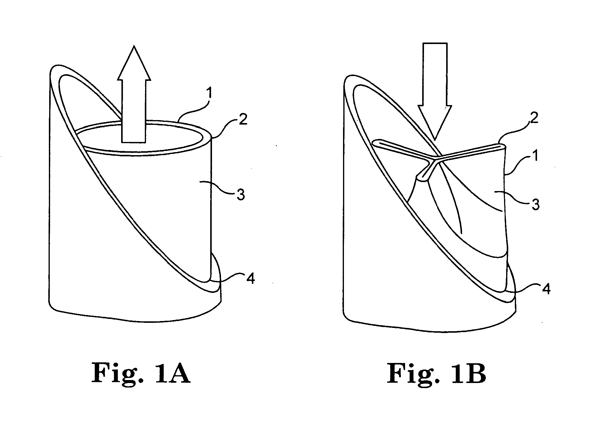
[0039]The present invention relates to methods, systems, and devices for reducing paravalvular leakage in heart valves. FIGS. 1A and 1B generally illustrate one exemplary embodiment of a heart valve 1. As illustrated in FIG. 1, valve 1 includes a distal outflow end 2, a plurality of leaflets 3, and a proximal inflow end 4. A typical valve functions similar to a collapsible tube in that it opens widely during systole or in response to muscular contraction to enable unobstructed forward flow across the valvular orifice, as illustrated in FIG. 1A. In contrast, as forward flow decelerates at the end of systole or contraction, the walls of the tube are forced centrally between the sites of attachment to the vessel wall and the valve closes completely as illustrated in FIG. 1B.

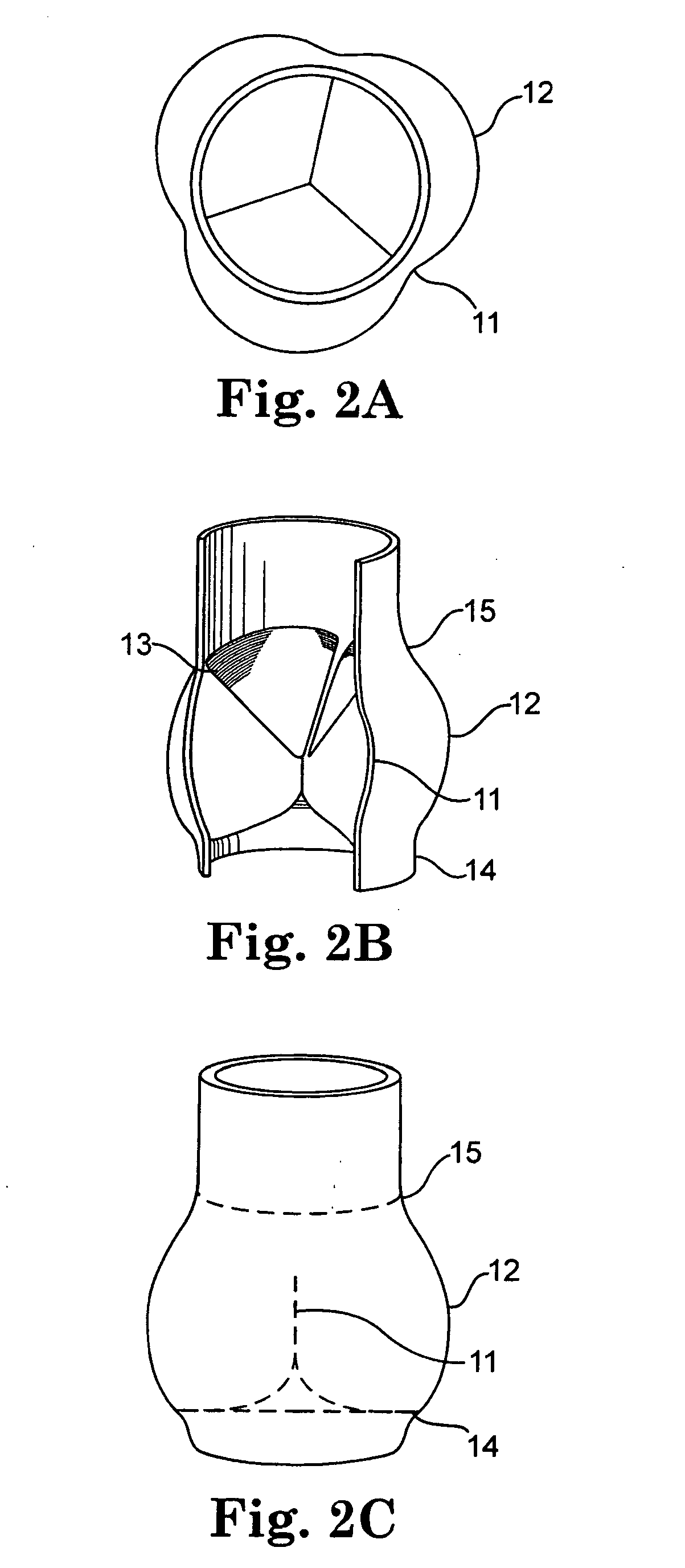
[0040]FIGS. 2A, 2B, and 2C illustrate the anatomy of a typical aortic valve. In particular, FIG. 2A shows a top view of a closed valve with three valve sinuses, FIG. 2B shows a perspective sectional view of the clos...


PUM


Abstract

A replacement valve comprises a valve body having an inflow end, an outflow end, and a valve support structure, and a valve cuff surrounding the inflow end of the valve body. The valve support structure surrounds the valve body, and the valve cuff is coupled to the valve support structure. The valve cuff includes a skirt portion and at least one flange coupled to and protruding from the skirt portion, the at least one flange forming a seal around the inflow end of the valve body.

Description

FIELD OF THE INVENTION[0001]The present invention relates generally to methods and systems for cardiovascular surgery. More particularly, the invention relates to reducing leakage around heart valves.BACKGROUND OF THE INVENTION[0002]The transport of vital fluids in the human body is largely regulated by valves. Physiological valves are designed to prevent the backflow of bodily fluids, such as blood, lymph, urine, bile, etc., thereby keeping the body's fluid dynamics unidirectional for proper homeostasis. For example, venous valves maintain the upward flow of blood, particularly from the lower extremities, back toward the heart, while lymphatic valves prevent the backflow of lymph within the lymph vessels, particularly those of the limbs.[0003]Because of their common function, valves share certain anatomical features despite variations in relative size. The cardiac valves are among the largest valves in the body with diameters that may exceed 30 mm, while valves of the smaller veins...

Claims


Application Information

Patent Timeline
IPC IPC(8): A61F2/24
CPCA61F2/2418A61F2230/0054A61F2220/005A61F2250/0069
Inventor TOOMES, CHRISNITZ, MARCLEE, TRACEYBERGHEIM, BJARNEQUIJANO, RODOLFOELIZONDO, DAVID
Owner MEDTRONIC 3F THERAPEUTICS
Why Eureka
Try Eureka