Valved stent and heart valve with same

a valve and stent technology, applied in the field of valved stent and heart valve with same, can solve the problems of difficult positioning, paravalvular leakage, and inability to repair or improve the valve function, and achieve the effect of reducing paravalvular leakage and reducing paravalvular leakag

Inactive Publication Date: 2020-12-17
FUWAI HOSPITAL CHINESE ACAD OF MEDICAL SCI CAMS +1
View PDF0 Cites 1 Cited by
  • Summary
  • Abstract
  • Description
  • Claims
  • Application Information

AI Technical Summary

Benefits of technology

[0022](1) According to the valved stent provided by the embodiments of the present invention, the waist portion is disposed near the inflow end, which can ensure that after the valve is implanted into the human body, the valved stent has the characteristic of active and accurate positioning, an implantation position of the valve is limited to prevent the valve from shifting, while a contact area between the valve prosthesis and an in-situ aortic valve annulus is also increased, so as to play a role in reducing paravalvular leakage.
[0023](2) The heart valve provided by the present invention comprises a valved stent, a valve body and a skirt edge, wherein the valved stent has a waist portion, so that the heart valve has the characteristics of active positioning and self-adaption of an aortic valve annulus. In addition, the skirt edge for sealing the periphery of the valve is also disposed on the valved stent, and the skirt edge is disposed on a peripheral wall of the valved stent and connected with the valve body, which can play a role in fixing the valve body on the one hand; and on the other hand, the skirt edge is an elastomer, and can be coupled to the peripheral wall of the valved stent at any time, whether the valved stent is in a contracted state or an deployed state, which ensures contact with surrounding tissue, and further reduces paravalvular leakage.

Problems solved by technology

Heart valve prosthesis replacement is required when the heart valve has severely diseased and the valve function cannot be repaired or improved by the surgical repair or replacement of the valve.
However, the existing valve prosthesis stent has the problems of being difficult to position, inaccurate in matching between the edge of a valve leaflet and a sewing ring after positioning, and paravalvular leakage may occur.
In addition, when the heart valve is closed and blood pressure of the body is maintained, shifting of the heart valve can occur, which cannot meet the requirement for normal functions of the valve.

Method used


Image

  • Valved stent and heart valve with same
  • Valved stent and heart valve with same
  • Valved stent and heart valve with same

Examples


embodiment 1

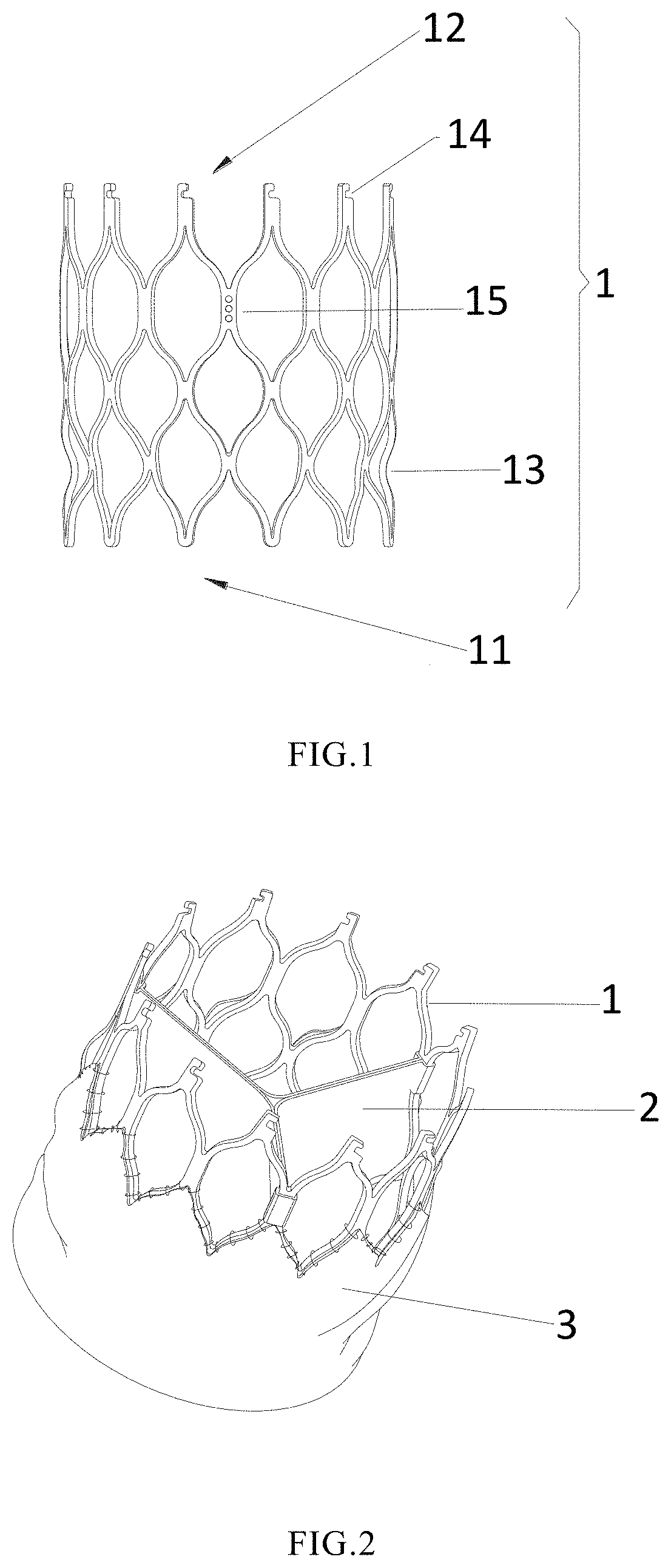
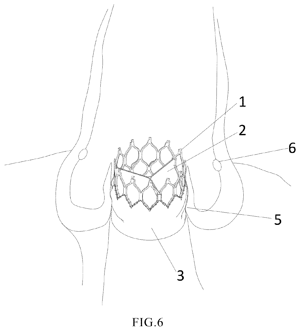
[0036]As shown in FIG. 1, the present invention provides a valved stent 1 having a cylindrical main body which can be formed by connection of a plurality of rhombic frames, can be radially contracted and deployed, and has an inflow end 11 and an outflow end 12, wherein a waist portion 13 is concavely formed near the inflow end 11 of the valved stent 1, that is, the waist portion 13 is positioned closer to the inflow end 11 than the outflow end 12, and a diameter of the waist portion 13 is slightly less than that of the inflow end 11 and the outflow end 12. When the valved stent 1 is implanted into a human body, the valved stent 1 can be actively clamped to a position of a valve annulus 5 to determine and limit a position of the valved stent 1. In addition, a connecting portion 14 is also disposed at the outflow end 12 and can be connected with an external delivery system, so that the valved stent 1 can be smoothly implanted into a human body. The delivery system described herein is ...

embodiment 2

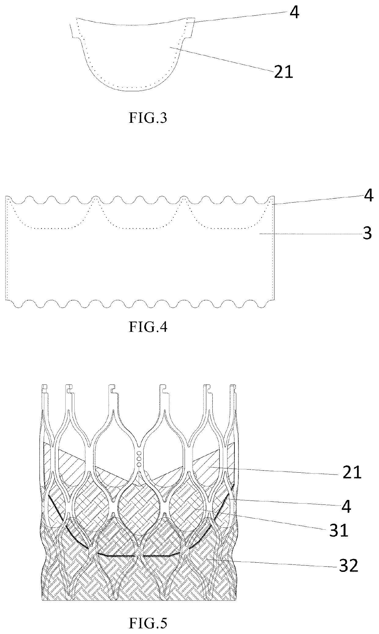
[0039]As shown in FIG. 2, the present invention provides a heart valve having a positioning setting. The heart valve comprises a valve body 2, a skirt edge 3 and the valved stent 1 described above, wherein the valve body 2 is disposed on an inner side of the valved stent 1, the skirt edge 3 is an elastomer, the elastomer is coupled to the valve body 2 and disposed on a peripheral wall of the valved stent 1 for sealing the periphery of the valve.

[0040]The heart valve provided by the present invention comprises a valved stent 1 with a waist portion 13, so that the heart valve has the characteristic of active positioning and self-adaption of an aortic valve annulus 5. In addition, a skirt edge for sealing the periphery of the valve is also disposed on the valved stent 1, and the skirt edge is disposed on the peripheral wall of the valved stent 1 and connected with the valve body 2, which can play a role in fixing the valve body 2 on the one hand; and on the other hand, the skirt edge 3...


PUM


Abstract

A valved stent is disclosed. The valved stent has an inflow end and an outflow end, a waist portion is concavely formed near the inflow end to determine and limit a position of the valved stent, and a connecting portion is disposed at the outflow end and used for being connected with a delivery system. The heart valve comprises a valve body, a skirt edge and the valved stent, wherein the valve body is disposed on an inner side of the valved stent, the skirt edge is an elastomer, and the elastomer is coupled to the valve body and disposed on a peripheral wall of the valved stent for sealing the periphery of the valve. The heart valve has the function of active positioning, and can effectively prevent the positioned valved stent from shifting. The heart valve is characterized by active positioning and self-adaption of an aortic valve annulus.

Description

CROSS-REFERENCE TO RELATED APPLICATIONS[0001]This application claims priority to Chinese Patent Application 201910522068.9, filed Jun. 17, 2019, which is hereby incorporated by reference.FIELD OF THE INVENTION[0002]The invention relates to the technical field of medical instruments, in particular to a valved stent and a heart valve with same.BACKGROUND OF THE INVENTION[0003]A heart valve prosthesis is an artificial device that can be implanted into the heart to replace a heart valve (an aortic valve, a tricuspid valve and a mitral valve) and enable blood to flow unidirectionally, and has the function of a natural heart valve. Heart valve prosthesis replacement is required when the heart valve has severely diseased and the valve function cannot be repaired or improved by the surgical repair or replacement of the valve.[0004]Heart valve prostheses fall into two broad categories depending on its materials: mechanical heart valves completely made from artificial materials; and bioprosth...

Claims


Application Information

Patent Timeline
Patent Type & Authority Applications(United States)
IPC IPC(8): A61F2/24A61F2/848
CPCA61F2220/0083A61F2/848A61F2/2436A61F2/2418A61F2210/0014A61F2/2412A61F2/2466A61F2210/0076A61F2220/0075A61F2230/0054A61F2230/0069A61F2250/0039A61F2250/0069
Inventor ZHAO, XUANCHENGWU, YONGJIANLIU, QINGRONGQIU, KEJINCHANG, RENCAOZHANG, YUXIN
Owner FUWAI HOSPITAL CHINESE ACAD OF MEDICAL SCI CAMS
Why Eureka
Try Eureka