Flat interface nerve electrode and a method for use

a nerve electrode and interface technology, applied in the field of soft tissue cuffs, can solve problems such as nerve flattening or other shape changes, and achieve the effect of significant flattening over time, without damage to the subject nerv

Inactive Publication Date: 2002-09-24
CASE WESTERN RESERVE UNIV
View PDF16 Cites 249 Cited by
  • Summary
  • Abstract
  • Description
  • Claims
  • Application Information

AI Technical Summary

Benefits of technology

The present invention contemplates a soft tissue cuff for use for example, as a nerve cuff electrode. The invention has application in addition for medicinal infusers and implantable biomedical devices for introducing, monitoring, or removing matter, fluids or energy. In contrast to prior art cuffs, the present invention is intended to apply a small, non-circumferiential force over time; this results in a non-damaging pressure within the intrafascicular endonurium so as to effect the nerve shape but not as to occlude blood flow within the nerve. The cuffs of the present invention may be implanted without damage to the subject nerve. Further, the cuff can allow for tissue swelling and movement. The present invention causes the nerve to mimic its natural reaction to forces applied within the body. Specifically, the body naturally applies small forces to the nerves which results in flattening or other shape changes to the nerve. An example of these forces is illustrated by the flattening of the sciatic nerve as it exits the pelvis at the sciatic foramen. Further, some nerves will take on an ellipsoidal shape as they pass through muscle planes. Other nerves have demonstrated significant flattening over time as a result of tumor pressure.

Problems solved by technology

Specifically, the body naturally applies small forces to the nerves which results in flattening or other shape changes to the nerve.

Method used


Image

  • Flat interface nerve electrode and a method for use
  • Flat interface nerve electrode and a method for use
  • Flat interface nerve electrode and a method for use

Examples


example ii

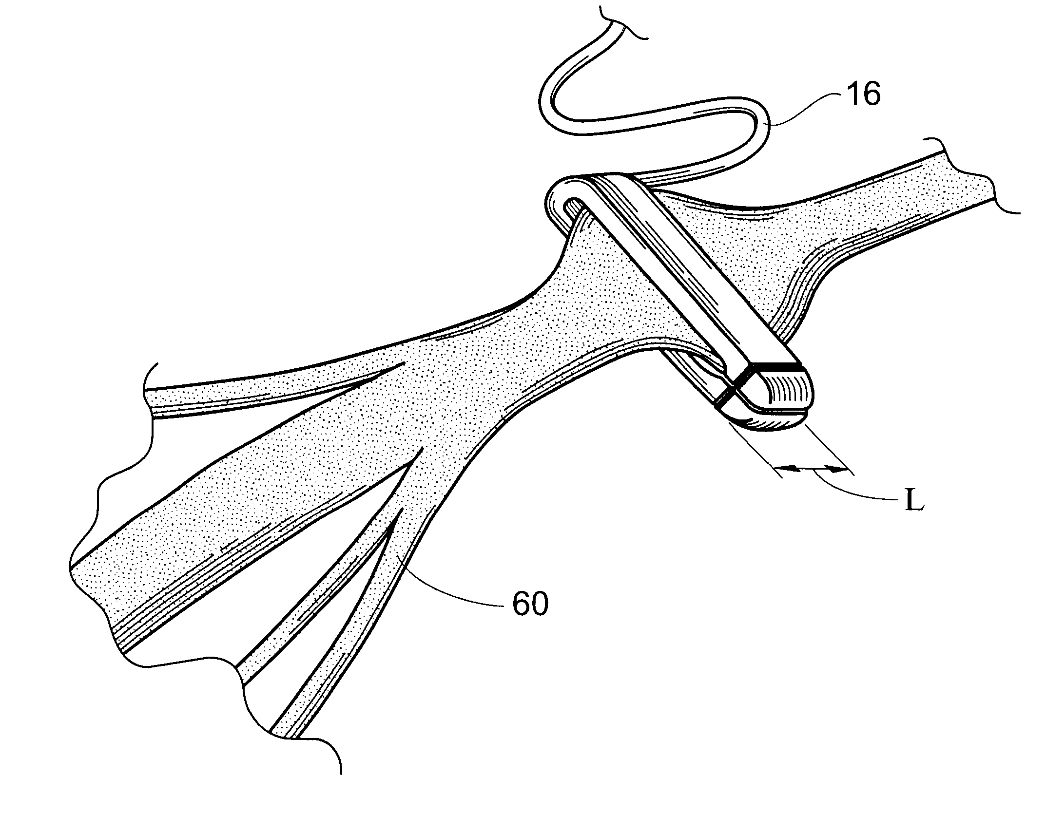
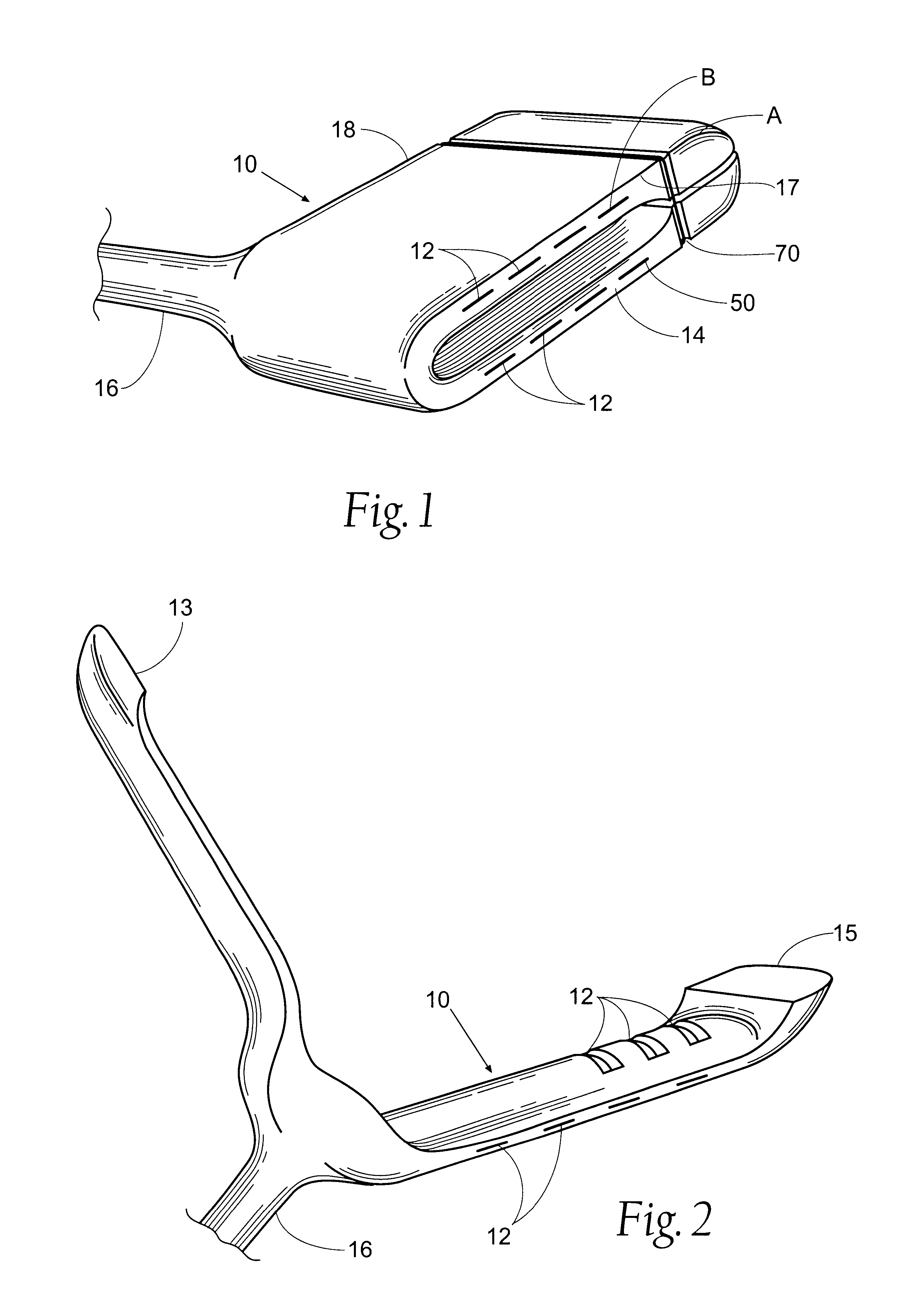
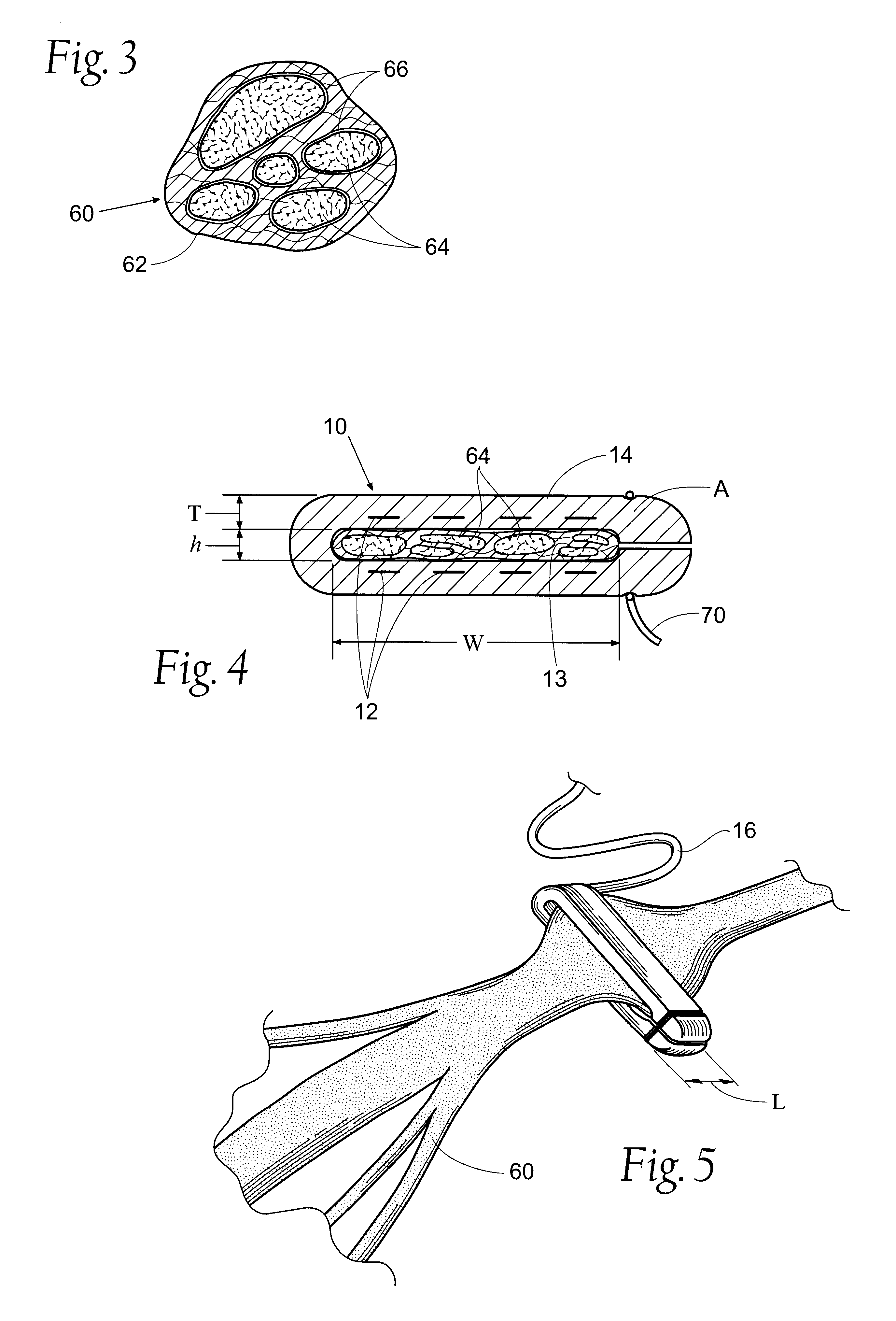
FINE electrodes were also implanted chronically on the sciatic nerve of 40 rats. FINEs of three different wall thickness, t in FIG. 4, (FIG. 2), were implanted for 1, 7, and 28 days and compared to sham implants. The thicker the wall thickness, the greater the force applied to the nerve. Nerve physiology was assessed weekly by measurements of the footprint during normal gait. Only the FINE with the greatest wall thickness produced any changes in the nerve physiology. The changes were significantly different (p<0.05, two-tail t-test of the mean) from the sham trials only between 1 and 14 days post-implant and had recovered by 21 days post-implant. Measurement of nerve geometry demonstrated that all three FINE designs significantly reshaped the nerve and fascicles compared to sham (p<0.05, Wilcoxon Rank-sum test of eccentricity measurements).

The histology of sham trials was not different than the histology from nerves implanted with the smallest wall thickness FINE. The FINE with the ...


PUM


Abstract

A flat interface nerve electrode is provided along with a method for its use. The electrode provides a plurality of conductive elements embedded in a non-conductive cuff structure, which acts to gently and non-evasively redefine the geometry of a nerve through the application of a force so as to apply pressure to a nerve in a defined range, namely from 2 to 40 mmHG and more preferably from 15 to 30 mmHG and most preferably from 15 mmHG to 20 MMHG. This range is selected to minimize the reduction of blood flow within the tissue, which preferably is at least 70% of the initial value, more preferably 90% of the initial value. The cuff has an opening, which is elongated relative to the diameter of the nerve to which it is applied. Preferably, the cuff is constructed from an elastic bio-compatible material having top and bottom beam members configured to define a nerve opening. The cuff is open at one side and has a connection at the other side which results in a spring force being applied through the surfaces of the nerve opening to the subject nerve. During implantation the open sides of the cuff are closed so as to capture the nerve in the cuff. As the nerve is reshaped, specific nerve axons become more easily addressed through the epineurium by the embedded conductive elements.

Description

The invention relates to implantable biomedical interfaces, and more particularly to a cuff for biological soft tissue which can be used as an electrode for selective stimulation and / or monitoring of nerve groups. Likewise, the cuff can be used as a delivery system for localized application of medication, such as bachlofin. The cuff also has application for use as a sensor for chemical removal.As the level of sophistication has increased in biomedical arts, advances have been made in implantable therapies. Therapies have evolved which involve the precise application of stimulus including electrical stimulus medication.This invention relates in particular to a nerve electrode cuff for use in functional electrical stimulation. Functional electrical stimulation of the nervous system can be used to help to restore or maintain some degree of lost sensory and motor function in neurologically impaired individuals. In addition, there are certain specialized applications, such as the treatme...

Claims


Application Information

Patent Timeline
Patent Type & Authority Patents(United States)
IPC IPC(8): A61B5/04A61N1/05
CPCA61B5/04001A61N1/0556A61B5/24
Inventor TYLER, DUSTINDURAND, DOMINIQUE M.
Owner CASE WESTERN RESERVE UNIV
Why Eureka
Try Eureka