Downhole isolation valve and methods for use

a technology of isolation valve and downhole, applied in the field of downhole tools, can solve the problems of adding complexity to the overall effort, requiring additional time and effort, and each trip consuming additional time and effort, and achieve the effect of facilitating the movement of the valve member

Active Publication Date: 2011-06-21
WELLS FARGO BANK NAT ASSOC +1
View PDF21 Cites 73 Cited by
  • Summary
  • Abstract
  • Description
  • Claims
  • Application Information

AI Technical Summary

Benefits of technology

[0013]at least one valve retainer operatively coupled between the fluid chamber and the valve member, the valve retainer configured to move in response to the communicated fluid pressure and thereby facilitate movement of the valve member from the first position to the second position.

Problems solved by technology

Each trip takes additional time and effort and adds complexity to the overall effort.

Method used


Image

  • Downhole isolation valve and methods for use
  • Downhole isolation valve and methods for use
  • Downhole isolation valve and methods for use

Examples


Embodiment Construction

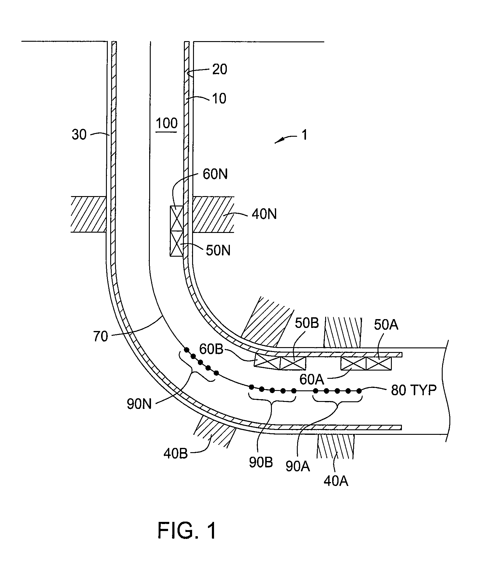
[0024]FIG. 1 shows a schematic view of a cased wellbore 1. The casing 10 is positioned inside the wellbore 1. An annulus 30 between the casing 10 and the wellbore 1 is typically filled with cement (not shown) in order to anchor the casing and isolate one or more production zones 40A-N, or formations. “A-N” is used herein to indicate a variable number of items so designated, where the number of such items may be one or more up to and including any number “N”. Optionally, any item designated with the suffix “A-N” may include one or more whether or not the suffix is used in a given context. In one embodiment, one or more tools 50A-N is located in the casing string. Each of the tools 50A-N includes a fluid reservoir or chamber 60A-N for operating the respective tool 50A-N, as will be described in more detail below. An energetic device 90 or devices 90A-N are shown located within the casing 10. The one or more energetic devices 90A-N may comprise any suitable deformation and / or perforati...


PUM


Abstract

A method and apparatus for actuating a downhole tool in a wellbore. The method and apparatus including an actuator that operates the tool in response to the functioning of an energetic charge. The energetic charge may be set off as a part of a perforating operation.

Description

BACKGROUND OF THE INVENTION[0001]1. Field of the Invention[0002]Embodiments of the present invention generally relate to downhole tools and methods for operating downhole tools. More particularly, embodiments of the present invention relate to apparatus and methods for actuating downhole tools in response to perforating a downhole tubular. More particularly still, embodiments of the present invention relate to apparatus and methods for actuating a downhole valve using a chemically energetic charge.[0003]2. Description of the Related Art[0004]In the drilling of oil and gas wells, a wellbore is formed using a drill bit disposed at a lower end of a drill string that is urged downwardly into the earth. After drilling a predetermined depth, the drill string and bit are removed and the wellbore is lined with a string of casing. An annular area is thereby formed between the string of casing and the formation. A cementing operation is then conducted in order to fill the annular area with ce...

Claims


Application Information

Patent Timeline
Patent Type & Authority Patents(United States)
IPC IPC(8): E21B29/00E21B33/10E21B34/06E21B43/112
CPCE21B34/08E21B34/063
Inventor GEORGE, KEVIN R.
Owner WELLS FARGO BANK NAT ASSOC
Why Eureka
Try Eureka