Vehicle seats

a technology for vehicles and seats, applied in the field of vehicles with air blowers, can solve the problems of inability to substantially reduce the volume of the air chamber formed in front of the air blower, and the upper portion cannot substantially deform, so as to achieve the effect of large capacity, reduced volume and increased thickness

Active Publication Date: 2011-06-21
TOYOTA BOSHOKU KK +1
View PDF23 Cites 114 Cited by
  • Summary
  • Abstract
  • Description
  • Claims
  • Application Information

AI Technical Summary

Benefits of technology

[0012]Further, an air chamber formed in front of the air blower cannot substantially be reduced in volume even if the central portion of the seat back is deformed. Therefore, it is not necessary to form the air chamber having large capacity in anticipation of volume reduction thereof caused by the deformation of the seat back. As a result, the air blower can be attached to the seat back without increasing thickness thereof.
[0013]In one embodiment, the air blower is connected to a back frame of the seat back via a bracket. That is, the air blower is not attached to an elastic member of the seat back. Therefore, the elastic member can be effectively prevented from resonating with vibration caused by rotation of the air blower. As a result, resonantly-generated vibration of the elastic member can be prevented.
[0014]In another embodiment, the air blower comprises a centrifugal air blower. Therefore, it is not necessary to provide the air chamber having large capacity. As a result, the air blower can be attached to the seat back without increasing thickness of the seat back.
[0015]In a further embodiment, the blowhole is formed in a back pad of the seat back. Further, the blowhole is arranged so as to open at each side of a pullin groove formed in the back pad. Therefore, the air can be effectively and widely sent toward the back of the passenger.

Problems solved by technology

Even if a central portion of the seat back is deformed, the seat back upper portion cannot substantially be deformed.
Further, an air chamber formed in front of the air blower cannot substantially be reduced in volume even if the central portion of the seat back is deformed.

Method used


Image

  • Vehicle seats
  • Vehicle seats
  • Vehicle seats

Examples


Embodiment Construction

[0021]A representative example of the present invention has been described in detail with reference to the attached drawings. This detailed description is merely intended to teach a person of skill in the art further details for practicing preferred aspects of the present invention and is not intended to limit the scope of the invention. Only the claims define the scope of the claimed invention. Therefore, combinations of features and steps disclosed in the foregoing detail description may not be necessary to practice the invention in the broadest sense, and are instead taught merely to particularly describe detailed representative examples of the invention. Moreover, the various features taught in this specification may be combined in ways that are not specifically enumerated in order to obtain additional useful embodiments of the present invention.

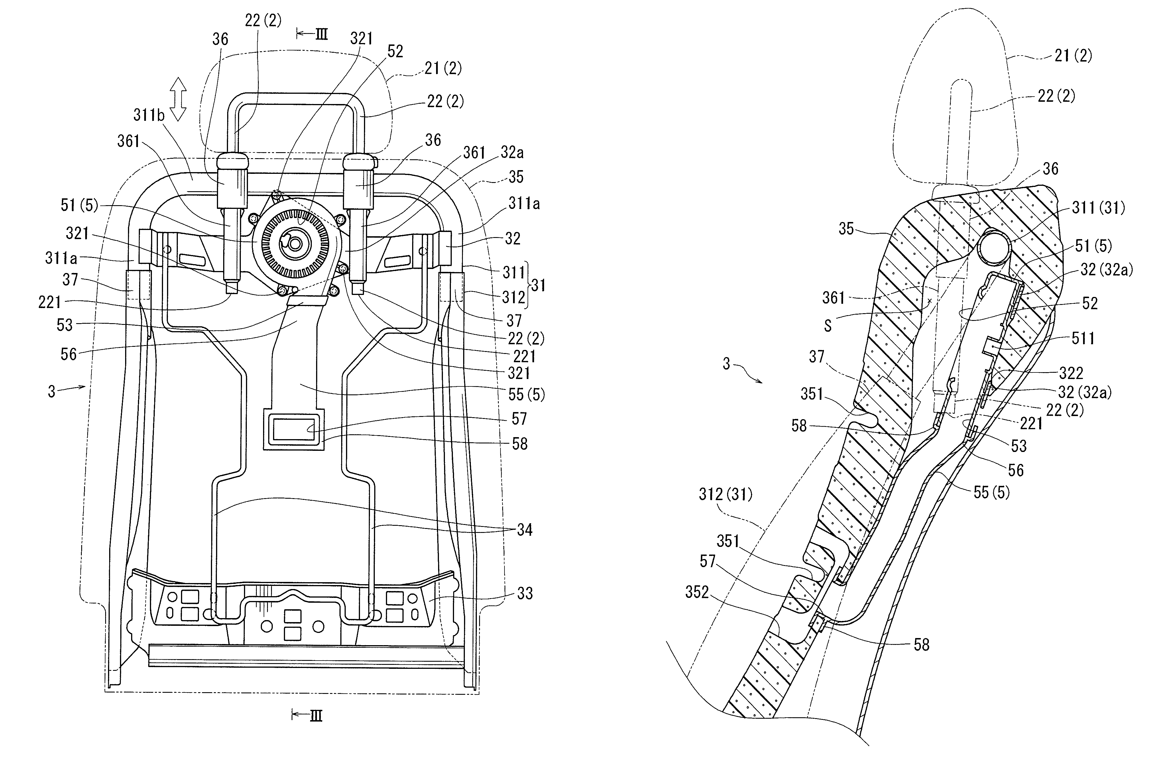
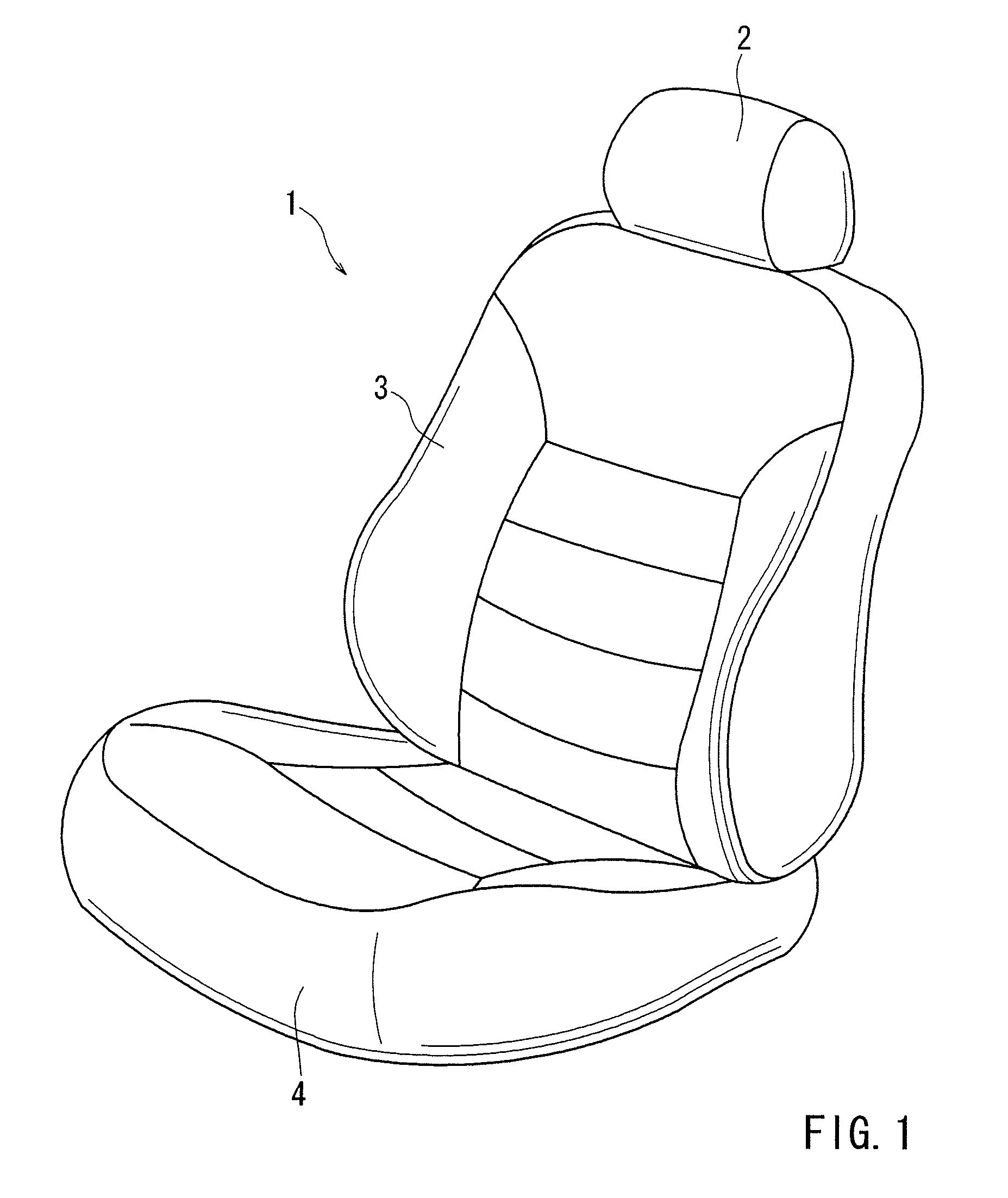
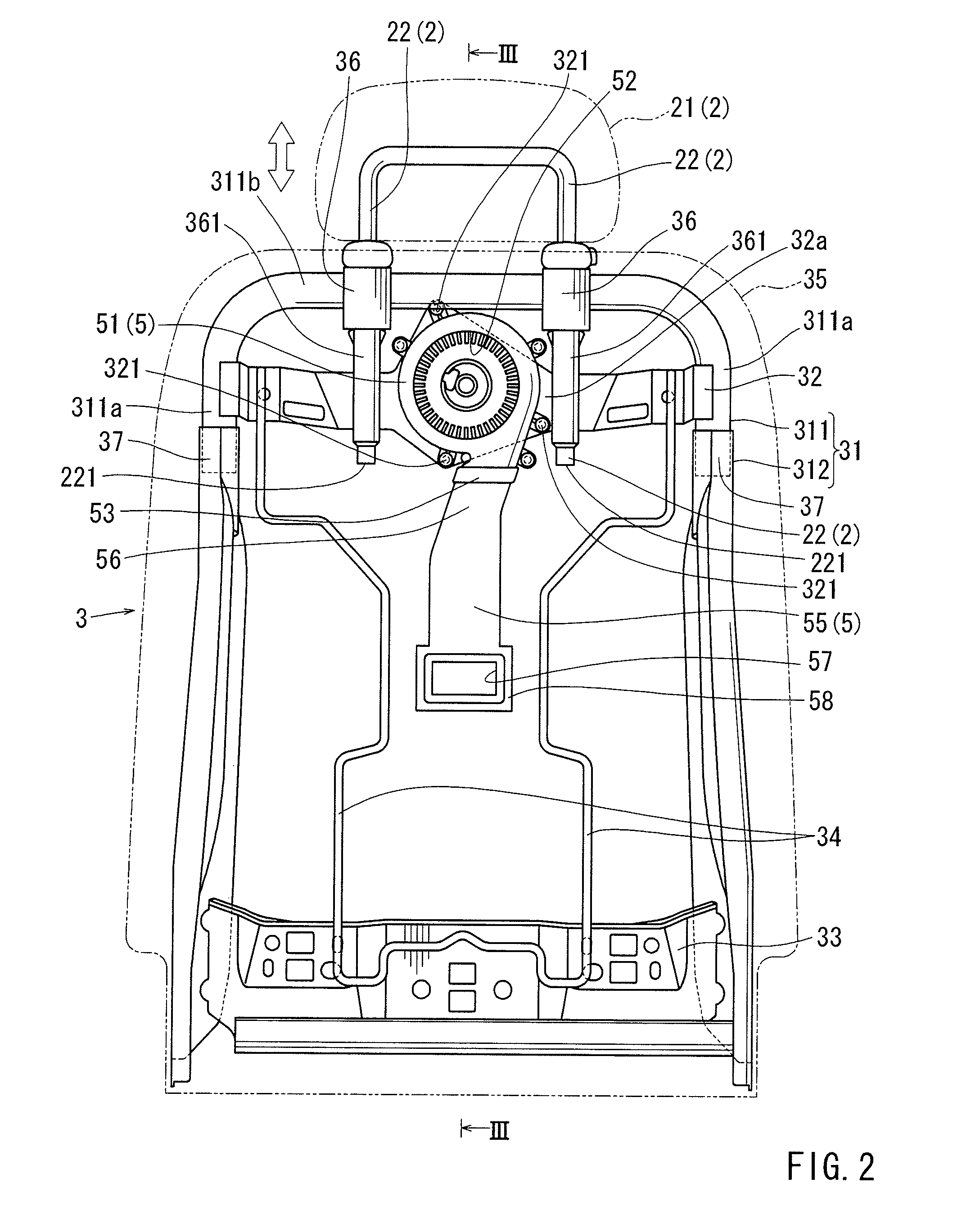
[0022]A detailed representative embodiment of the present invention will be described with reference FIGS. 1 to 4.

[0023]Further, forwar...


PUM


Abstract

A vehicle seat includes a seat back and a head rest. The seat back has an air blower that is capable of aspirating air, and a blower duct that is capable of introducing the aspirated air toward a blowhole formed in the seat back. The head rest has a head rest main body and a stay attached to the head rest main body. The stay is inserted into the seat back, so that the head rest main body is vertically movably attached to the seat back. The air blower is disposed on the seat back such that a rotation center thereof can be positioned above the level of a terminal end of the stay that is moved to a lowermost position.

Description

[0001]This application claims priority to Japanese patent application serial number 2008-145952, the contents of which are incorporated herein by reference.BACKGROUND OF THE INVENTION[0002]1. Field of the Invention[0003]The present invention relates to vehicle seats. More particularly, the present invention relates to vehicle seats having air blowers that can send air toward passengers sitting on the vehicle seats.[0004]2. Description of Related Art[0005]A vehicle seat having an air blower is already known. Such a vehicle seat is taught, for example, by Japanese Laid-Open Patent Publication No. 2005-34345. In the vehicle seat, the air blower is embedded in a seat back, so as to send air toward the back of a passenger sitting on the vehicle seat in order to provide cool air toward the passenger.[0006]Generally, in such a vehicle seat, the air blower is an axial-flow blower having an axial-flow fan and is disposed on a central portion of the seat back. Therefore, it is necessary to fo...

Claims


Application Information

Patent Timeline
Patent Type & Authority Patents(United States)
IPC IPC(8): A47C7/74B60N2/90
CPCB60N2/5657B60N2/4808B60N2/809
Inventor ITO, HIDEHIROMORI, HISAYANIIMI, YASUHIKOITO, YUJI
Owner TOYOTA BOSHOKU KK
Why Eureka
Try Eureka