Panoramic Imaging Device

a technology of panoramic imaging and imaging device, which is applied in the field of panoramic imaging device, can solve the problems of unnatural transition between adjacent images, and the likely periphery of panoramic images captured by such imaging devices, and achieve the effect of reducing volume and thickness

Inactive Publication Date: 2007-10-18
FUNAI ELECTRIC CO LTD
View PDF2 Cites 8 Cited by
  • Summary
  • Abstract
  • Description
  • Claims
  • Application Information

AI Technical Summary

Benefits of technology

[0008]An object of the present invention is to provide a panoramic imaging device for capturing a panoramic image with a picture angle of at least 120°, which can be formed by a minimum number of optical systems without using an optical lens having a capture ang...

Problems solved by technology

However, the panoramic image captured by such imaging device is likely to have barrel distortion at periphery thereof.
However, this leads to a disadvantage in that images formed by using lenses having a capture angle greater than 60° are likely to have barrel distortions at peripheries thereof as described above, and that the barrel distortions cause unnatural transition ...

Method used


Image

  • Panoramic Imaging Device
  • Panoramic Imaging Device
  • Panoramic Imaging Device

Examples


first embodiment

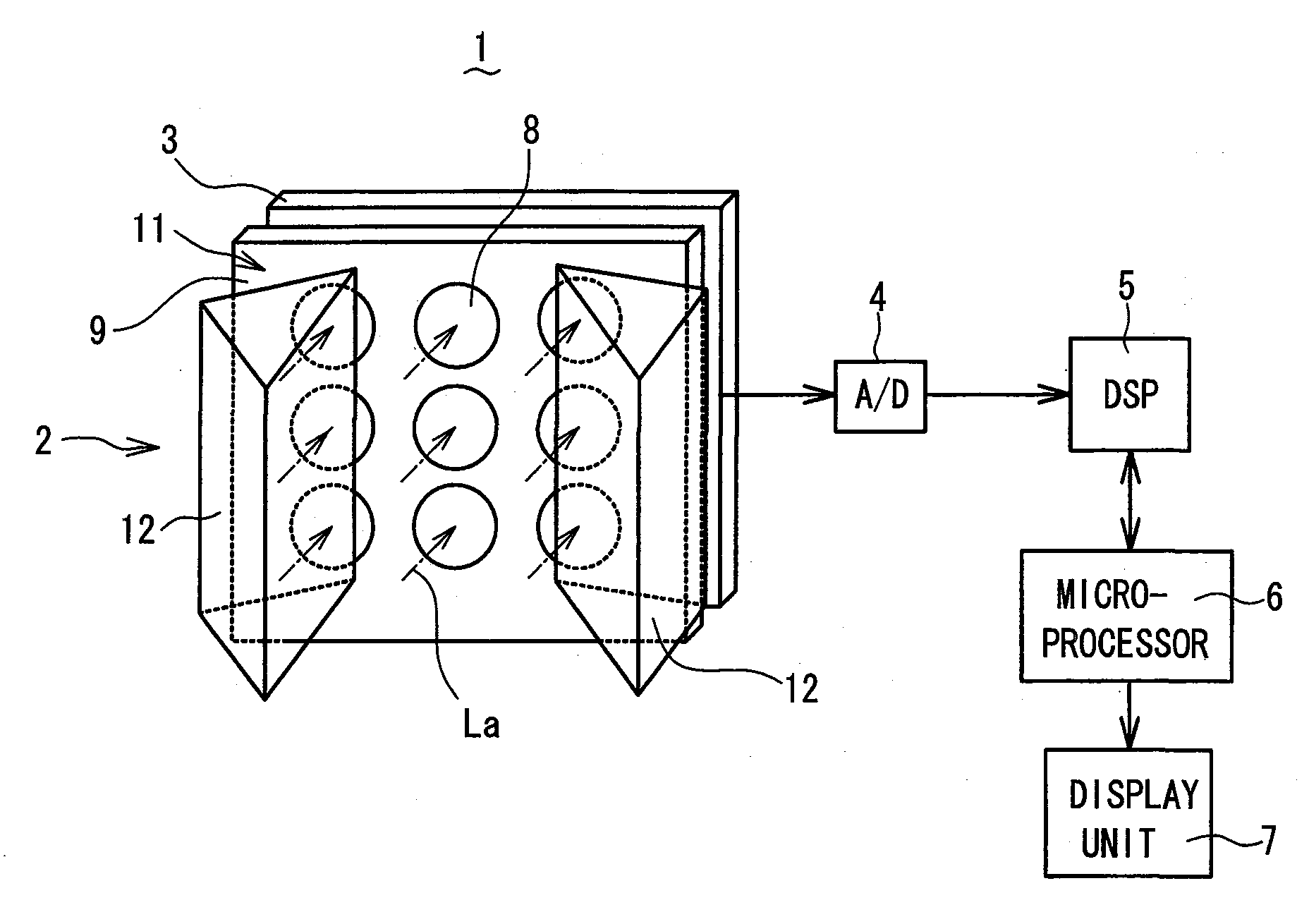
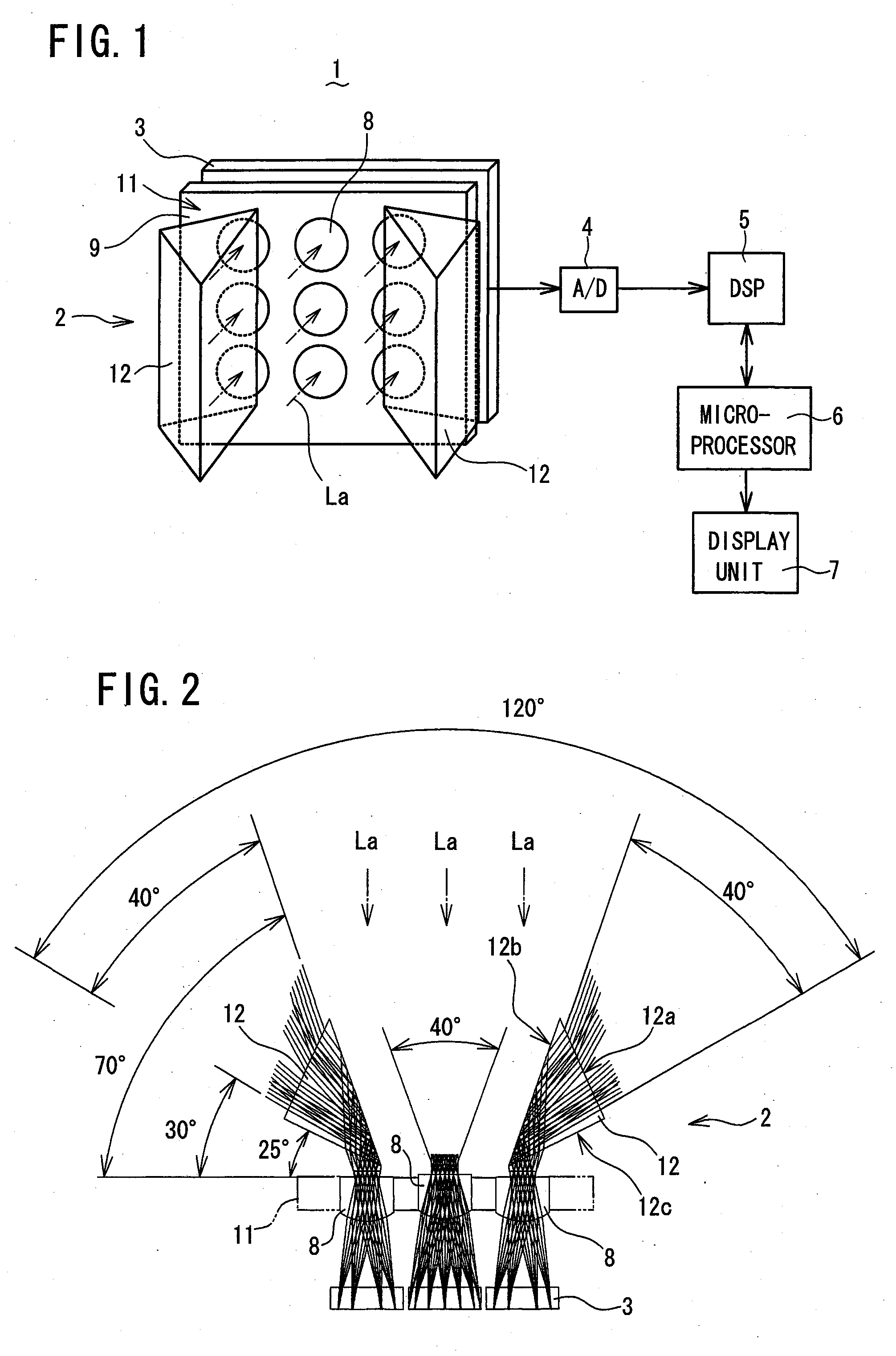
[0037]Referring to FIG. 1 to FIG. 5, a panoramic imaging device 1 according to a first embodiment of the present invention will be described. FIG. 1 is a schematic perspective view of the panoramic imaging device 1 including an optical lens system 2 having optical lenses 8 and a photodetector array 3 along with a processing circuit, in block diagram form, for signal processing and display, while FIG. 2 is a schematic optical path diagram of the optical lens system 2 of FIG. 1 as seen from the bottom thereof, showing a light flux passing through each optical lens 8.

[0038]As shown in FIG. 1 and FIG. 2, the panoramic imaging device 1 according to the present embodiment comprises: an optical lens system 2 for collecting light entering therein in a capture angle (picture-taking angle) of 120° (substantially 120°) so as to form images on a predetermined focal plane; a photodetector array (claimed “imaging means”) 3 placed at the focal plane of the optical lens system 2 for converting the ...

second embodiment

[0053]Referring to FIG. 6 and FIG. 7, a panoramic imaging device according to a second embodiment of the present invention will be described. FIG. 6 is a schematic front view of an optical lens system 2 of a panoramic imaging device according to the second embodiment, in which showing of the other parts corresponding to those in FIG. 1, such as a processing circuit including a DSP and an image reproduction microprocessor, is omitted for simplicity. FIG. 7 is a schematic optical path diagram of the optical lens system 2 of FIG. 6 as seen from the bottom thereof, showing a light flux passing through each optical lens 8. Similarly as in the first embodiment, the optical lens system 2 has an optical lens array 11 of optical lenses 8 and a photodetector array 3. In the drawings of the first and second embodiments, like parts are designated by like reference numerals, characters or symbols. Here, description of parts similar to those in the first embodiment is omitted where appropriate.

[0...

third embodiment

[0057]Referring to FIG. 8 and FIG. 9, a panoramic imaging device according to a third embodiment of the present invention will be described, which can capture or take a panoramic image with a picture angle of approximately 180°. FIG. 8 is a schematic front view of an optical lens system 2 of a panoramic imaging device according to the third embodiment, in which showing of the other parts corresponding to those in FIG. 1, such as a processing circuit including a DSP and an image reproduction microprocessor, is omitted for simplicity. FIG. 9 is a schematic optical path diagram of the optical lens system 2 of FIG. 8 as seen from the bottom thereof, showing a light flux passing through each optical lens 8. Similarly as in the first embodiment, the optical lens system 2 has an optical lens array 11 of optical lenses 8 and a photodetector array 3. In the drawings of the first and third embodiments, like parts are designated by like reference numerals, characters or symbols. In the third e...


PUM


Abstract

A panoramic imaging device comprises: a lens array having a center lens for receiving light entering in a front range of at most 60° in a capture angle and left and right side lenses formed on the same plane as that with the center lens formed thereon and having optical axes parallel to that of the center lens for receiving lights entering in left and right ranges each of at most 60° in the capture angle; and prisms or mirrors placed on light entrance side of the lens array for guiding and reflecting lights entering in the left and right ranges, such that each light entering each side lens is directed along the optical axis of each side lens. Images formed by the center lens and the left and right side lenses are combined into a panoramic image with a picture angle of at least 120°.

Description

BACKGROUND OF THE INVENTION[0001]1. Field of the Invention[0002]The present invention relates to a panoramic imaging device.[0003]2. Description of the Related Art[0004]It is known to use an imaging device having an ultra-wide-angle optical system such as a fisheye lens to capture or take a panoramic image with a picture angle greater than 120° (degrees). However, the panoramic image captured by such imaging device is likely to have barrel distortion at periphery thereof. On the other hand, technologies have advanced to convert captured images to digital information, and process it. There are various imaging devices which have been developed to create a panoramic image based on such technologies, in which images in multiple picture-taking areas are captured by multiple optical systems positioned at predetermined angular positions for the respective picture-taking areas, and are combined into a panoramic image.[0005]For example, an imaging device is known which uses three optical sys...

Claims


Application Information

Patent Timeline
IPC IPC(8): G03B41/00
CPCG02B3/0006G02B5/04G02B13/06H04N5/2624G03B37/04H04N5/2254G03B37/00H04N23/60
Inventor TOYODA, TAKASHINAKAO, YOSHIZUMIMASAKI, YASUO
Owner FUNAI ELECTRIC CO LTD
Why Eureka
Try Eureka