Back panel for video display device

a video display and back panel technology, applied in the field of televisions, can solve the problems of increasing the manufacturing cost of wiring the components together, reducing the production efficiency of flat panel displays, and reducing the effective thickness of displays. the effect of thinness, lightness and cost reduction

Inactive Publication Date: 2011-06-28
WESTINGHOUSE DIGITAL ELECTRONICS LLC
View PDF4 Cites 7 Cited by
  • Summary
  • Abstract
  • Description
  • Claims
  • Application Information

AI Technical Summary

Benefits of technology

[0010]A “bucket” or back housing for a flat panel television with thin center-mounted controller board and power supply is described. This back panel is an improvement on the prior art by allowing for the production of a thinner, lighter and cheaper to produce flat panel display overall. The bucket of the flat panel display has a centrally mounted “spine” in which all electronics, connectors, heat sink and the power supply are placed.
[0011]The flat panel display provides a very thin, front to back, screen area. The thickness required for the screen itself and the housing surrounding the screen are all that is necessary in the non-spine areas of the display. In the center of the display back, the main logic board and power supply are situated. The housing over this area also may be reinforced to allow the unit to be wall-mounted. The spine configuration of the display requires fewer separate components to be connected via wiring, requires less wiring to connect the components with the screen itself, and makes it such that the spine itself may be easily mass-produced and attached to multiple sizes and types of displays.

Problems solved by technology

In many cases the effective thickness of the display is further increased due to poor cable management.
The addition of these longer signal paths and corresponding connectors introduces visible and unnecessary electronic signal degradation and interference.
Additionally, the electronic components' scattered positions throughout the back of the display increase the manufacturing cost of wiring the components together.

Method used


Image

  • Back panel for video display device
  • Back panel for video display device
  • Back panel for video display device

Examples


Embodiment Construction

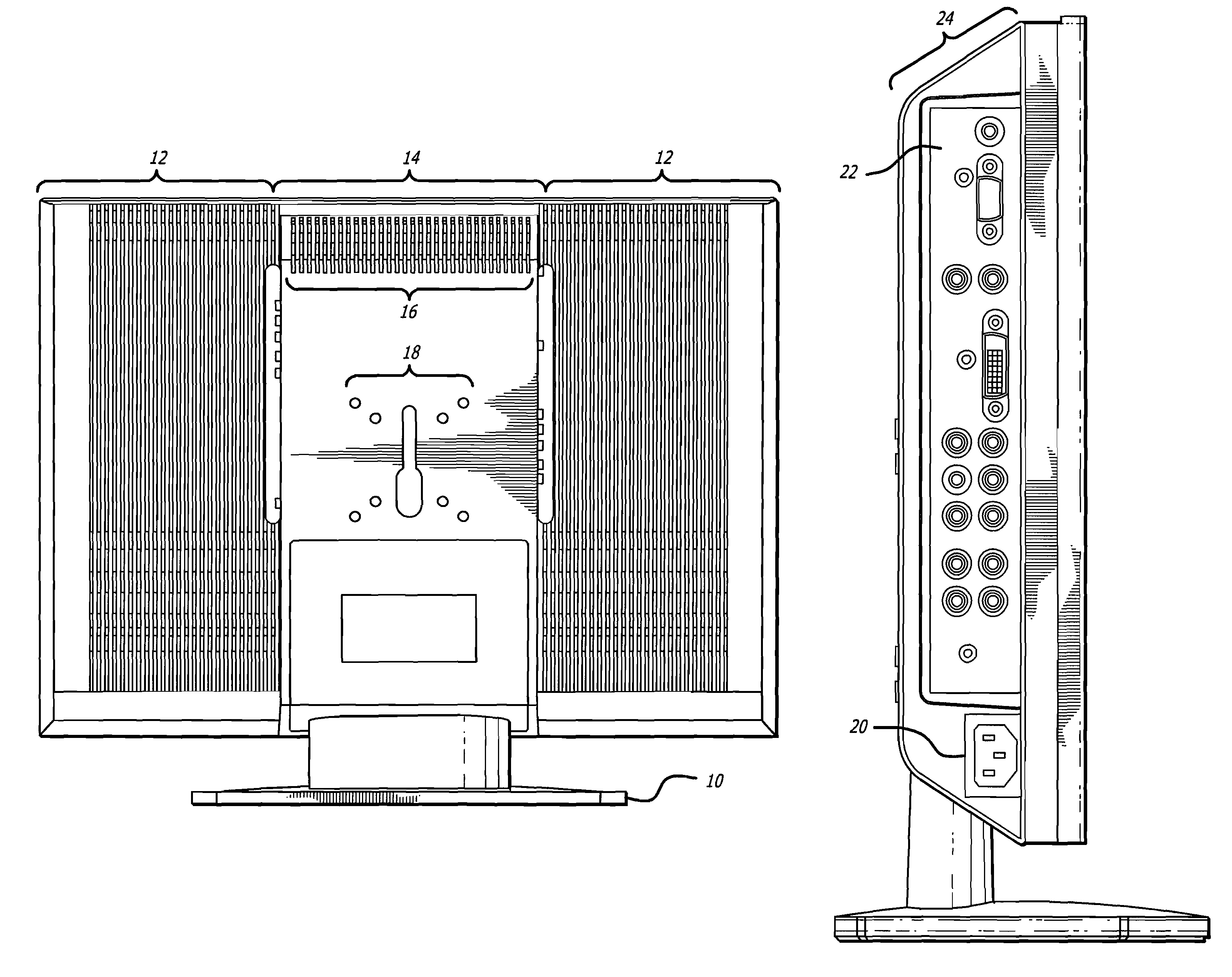
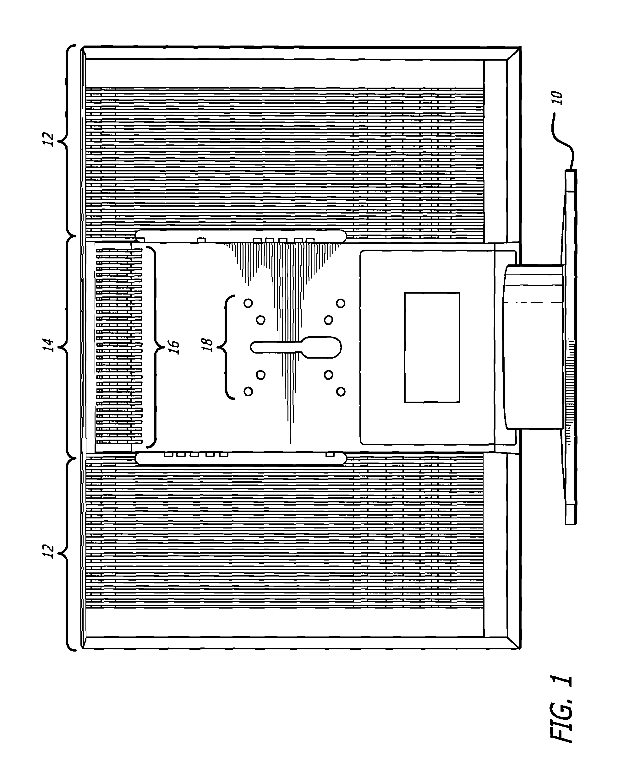
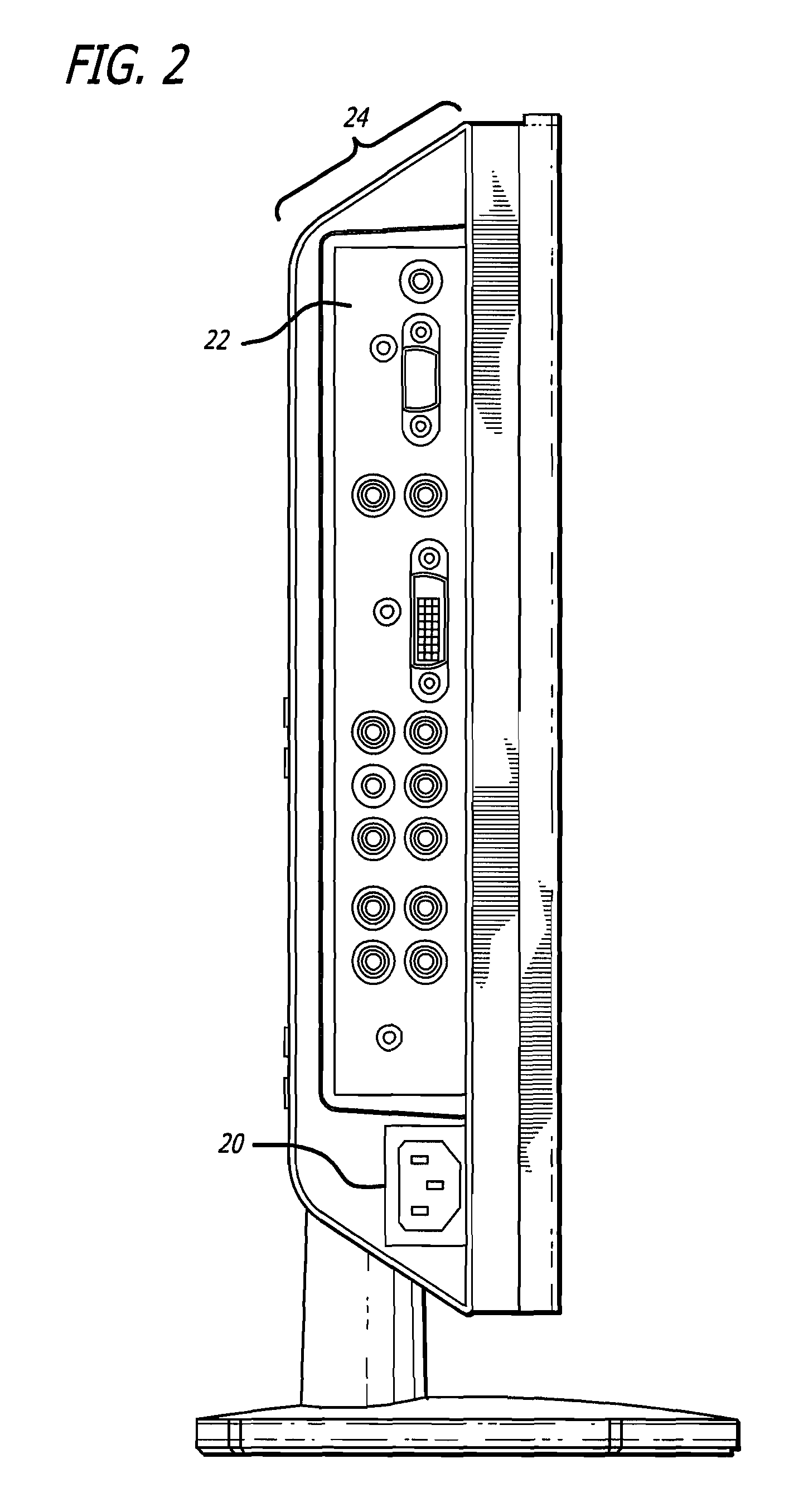
[0019]Referring first to FIG. 1, the back of a flat panel display is depicted. A base 10 may or may not be attached to a display. As is common in the art, the display may be used free-standing or hung on a wall. The base 10 is shown, for purposes of example, attached in this figure. Notably, the base 10 is attached only to the spine 14 of the television. In the preferred method of this invention a single connector type will be needed to attach a base 10 to any size of television using the spine 14. There are standardized connectors enclosed within the spine 14 which may be attached to multiple bases. Side panels 12 are very thin, front to back. In the preferred embodiment, the side panels 12 are only thick enough to provide a housing for the display. There are also cooling vents in the side panels 12 situated at the top and near the bottom. Liquid crystal displays do not generate much heat, nor do plasma display technology. However, the main controller board and electronics involved...


PUM


Abstract

A back panel for a display device, such as a flat-panel television or computer monitor, which is very thin around the edges and houses all electronics in a “spine” near the vertical center of the back of the display. The back panel provides novel heat-dissipation, arrangement of electronics to save space, forces the center of gravity forward allowing the display to be set closer to a wall, and provides less interference and signal degradation than the prior art.

Description

CROSS-REFERENCE TO RELATED APPLICATIONS[0001]This invention claims priority based upon U.S. provisional patent application Ser. No. 60 / 756,169, filed Jan. 4, 2006 and entitled “Improved Back Panel for Video Display Device”. Application Ser. No. 60 / 756,169 is incorporated thereto in its entirety herein by reference.BACKGROUND[0002]1. Field of the Invention[0003]The present invention relates to televisions and more particularly to an improved back center panel for video display device. The invention is a thin centrally-mounted back solution for a flat panel display that houses all electronics and connectors for the display. The central solution also contains the main controller board for the display and the power supply.[0004]2. Background of the Invention[0005]Televisions have evolved from black and white, to color, and most recently into flat panels and high definition televisions. Through this process, the technology used to perform the various functions has progressed from clunky ...

Claims


Application Information

Patent Timeline
Patent Type & Authority Patents(United States)
IPC IPC(8): H05K5/00H05K7/00
CPCH05K7/20963G06F1/1601
Inventor CHANG, DARWINTONG, HING S.ARAKI, JOHN
Owner WESTINGHOUSE DIGITAL ELECTRONICS LLC
Why Eureka
Try Eureka