Device and method for relaying packets

a packet and device technology, applied in the field of devices and methods for relaying packets, can solve the problems of communication load imbalance, communication load imbalance, and communication load imbalance that cannot be alleviated, and achieve the effect of reducing communication load imbalan

Active Publication Date: 2011-06-28
ALAXALA NETWORKS
View PDF7 Cites 49 Cited by
  • Summary
  • Abstract
  • Description
  • Claims
  • Application Information

AI Technical Summary

Benefits of technology

[0007]An object of the invention is to provide a technology capable of alleviating communication load imbalance.

Problems solved by technology

As a result, in some instances, communication load imbalance will not be alleviated.
Particularly in cases where network relay devices are directly connected, communication load imbalance in front end relay devices and communication load imbalance in back end relay devices may cumulatively result in appreciable communication load imbalance.
As a result, it is possible to avoid a situation where communication load imbalance in this network relay device and communication load imbalance in the other network relay device cumulatively result in appreciable communication load imbalance.

Method used


Image

  • Device and method for relaying packets
  • Device and method for relaying packets
  • Device and method for relaying packets

Examples


embodiment 1

A. Embodiment 1

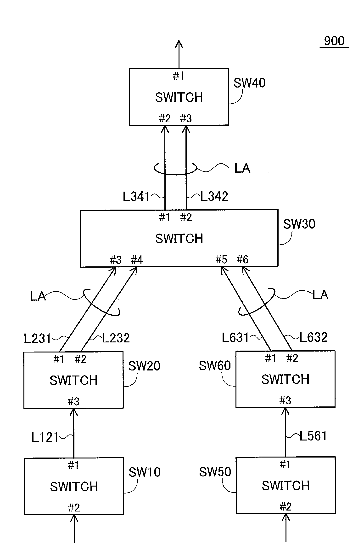
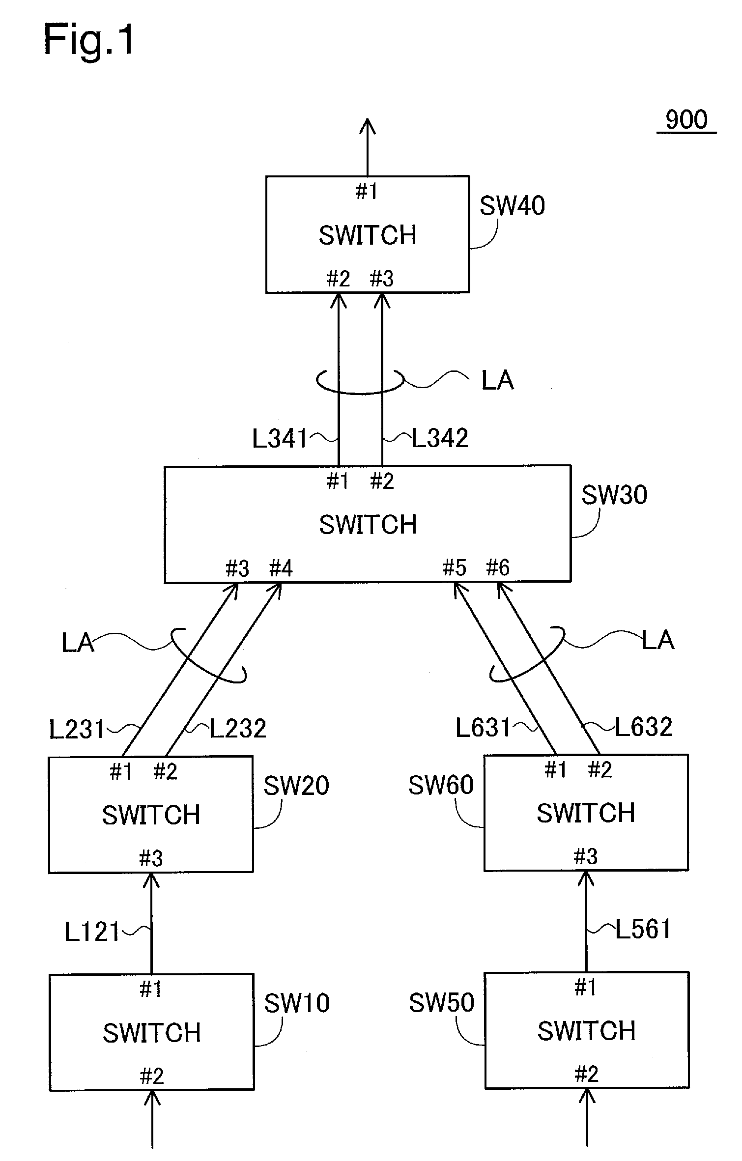
[0049]FIG. 1 is an illustration of a network system employing switch devices in an embodiment of the present invention. This network system 900 has six switch devices SW10 to SW60. In Embodiment 1, these switch devices SW10 to SW60 all function as “Layer 2 switches.”

[0050]Three of the switch devices SW20, SW40, and SW60 are connected to the third switch device SW30. The third switch device SW30 is respectively connected by two lines with the switch devices SW20, SW40, and SW60. The first switch device SW10 and the second switch device SW20 are connected by a single line L121; and the fifth switch device SW50 and the sixth switch device SW60 are connected by a single line L561.

[0051]The switch devices SW10 to SW60 have physical ports for the purpose of connecting to the lines. In FIG. 1, physical port numbers identifying the physical ports are denoted by a combination of the symbol “#” with a number. For example, the line L121 connecting the first switch device SW10 wi...

embodiment 2

[0106]FIG. 13 is an illustration depicting a network system 900c in Embodiment 2. This network system 900c has nine switch devices RT10 to RT90. In Embodiment 2, the switch devices RT10 to RT90 all function as “Layer 3 switches (also called routers).”

[0107]In this network system 900c, the first switch device RT10 and the seventh switch device RT70 are connected by four pathways PT1 to PT4. The first pathway PT1 is a pathway that leads from the first switch device RT10 through the three switch devices RT20, RT30, RT50 in that order, to arrive at the seventh switch device RT70. The second pathway PT2 is a pathway that leads from the first switch device RT10 through the three switch devices RT20, RT30, RT60 in that order, to arrive at the seventh switch device RT70. The third pathway PT3 is a pathway that leads from the first switch device RT10 through the two switch devices RT20, RT40 in that order, to arrive at the seventh switch device RT70. The fourth pathway PT4 is a pathway that ...

embodiment 3

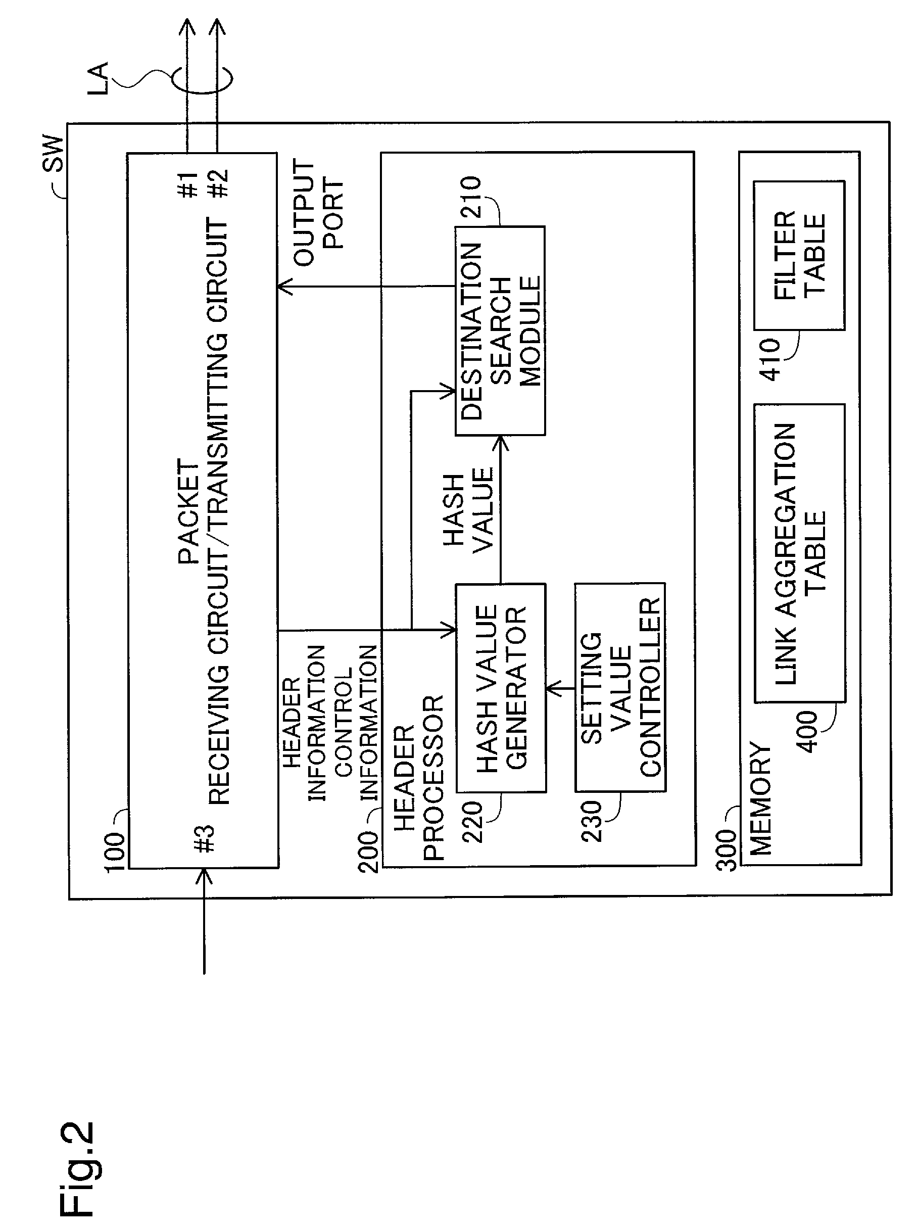
[0135]FIG. 16 is an illustration depicting the configuration of a header processor 200a in Embodiment 3. There are two points of difference from the header processor 200 of Embodiment 1 illustrated in FIG. 2. The first difference is that a function selector 240 is provided in place of the setting value controller 230. The second difference is that the hash value generator 220a is capable of utilizing three mutually different hash functions HF1 to HF3. The other configuration of the switch devices is the same as that of the switch devices SW of Embodiment 1 illustrated in FIG. 2. In FIG. 16, only the header processor 200a is shown by way of the constituent elements of the switch device; the other elements are omitted from the drawing.

[0136]The function selector 240 selects one hash function from among the three hash functions HF1 to HF3. The hash value generator 220a then computes hash values on the basis of the hash function selected by the function selector 240. Various mutually di...


PUM


Abstract

Computing process with a computational expression is executed using seed information including at least one of destination information and source information associated with a received packet. It is preferable to select a physical port for transmission of the received packet based on the result of the computation. It is also preferable to select a port group for transmission of the received packet based on the result of the computation. Here, the computational expression is capable of being modified. Meanwhile, the physical port for transmission of the received packet is selected from a plurality of candidate ports among the plurality of physical ports. The port group for transmission of the received packet is selected from among a plurality of port groups including a mutually different candidate port.

Description

CROSS-REFERENCE TO RELATED APPLICATIONS[0001]The present application claims the priority based on Japanese Patent Application No. 2006-219455 filed on Aug. 11, 2006, the disclosure of which is hereby incorporated by reference in its entirety.BACKGROUND[0002]1. Technical Field[0003]The present invention relates to a device and a method for relaying packets.[0004]2. Description of the Related Art[0005]Link aggregation based on the IEEE 802.3ad standard is a known redundant configuration for networks. Methods using multiple network relay devices (e.g. switch devices or router devices) to build redundant communication pathways are also known. A method for distributing the communication load, by using a function to convert information (e.g. the header of a frame being transmitted) into an output value, and on the basis of the output value, selecting a transmission cue corresponding to one of several links is also known (see Japanese Patent Published Application No. 2005-252758A). Another...

Claims


Application Information

Patent Timeline
Patent Type & Authority Patents(United States)
IPC IPC(8): G01R31/08H04L12/28H04L12/46
CPCH04L45/00H04L45/245Y02B60/33Y02D30/50
Inventor YANO, HIROKISUGAI, KAZUOAKAHANE, SHINICHINARA, TAKAO
Owner ALAXALA NETWORKS
Why Eureka
Try Eureka