Method and apparatus for compressing image data

a compression method and image data technology, applied in the field of apparatus and image data compression, can solve the problem that the configuration study is not enough to effectively perform the control of the generated code volume, and achieve the effect of suppressing the image data volum

Inactive Publication Date: 2011-06-28
KOKUSA ELECTRIC CO LTD
View PDF4 Cites 6 Cited by
  • Summary
  • Abstract
  • Description
  • Claims
  • Application Information

AI Technical Summary

Benefits of technology

[0006]It is therefore an object of the present invention to provide an image data compression apparatus capable of effectively suppressing an image data volume after the compression processing.
[0010]As has been described above, in the image data compression apparatus according to the present invention, the bit rate value is detected according to the image data volume after the compression processing; the quantization step size value used in the compression processing is changed according to the detected bit rate; the number of skip frames is set according to the quantization step size value; and the frame skip of the image data before or after the compression processing is performed according to the number of skip frames which has been set. Thus, it is possible to effectively suppress the image data volume after the compression processing.

Problems solved by technology

Here, in the conventional moving image compression apparatus, sufficient study has not been performed on configuration for effectively performing control of a generated code volume.

Method used


Image

  • Method and apparatus for compressing image data
  • Method and apparatus for compressing image data
  • Method and apparatus for compressing image data

Examples


first embodiment

[0020]Explanation will be given on the first embodiment of the present invention.

[0021]FIG. 7 shows a moving image compression apparatus according to the embodiment of the present invention.

[0022]The moving image compression apparatus shown in FIG. 7 includes a frame selector 1, an image compressor 2, an output buffer 3, and a bit rate controller 15.

[0023]When a frame skip instruction signal 13 is inputted from the bit rate controller 15, the frame selector 1 performs a frame skip (frame discarding) of input image data 6. Otherwise, the frame selector 1 outputs the input image data 6 to the image compressor 2.

[0024]The image compressor 2 performs compression of the input image data 6 by a predetermined compression method such as the MPEG (Moving Picture Experts Group) method and the Motion-JPEG (Joint Photographic Experts Group) method and outputs the compressed data to the output buffer 3. Here, the compression processing by the image compressor 2 is performed according to a Q-valu...

second embodiment

[0038]In the moving image compression, the generated code volume 9 is increased or decreased by the complexity of the input image. If the timing of frame skip depends on increase / decrease of the generated code volume 9, the next timing when the frame skip is performed is not constant. For this, in the motion of the moving image in the display device receiving the compressed data 7, a frame skip is caused at irregular intervals. This damages the smoothness of motion in the moving image display.

[0039]Accordingly, when more weight is given on the motion smoothness rather than the image quality, the second embodiment which will be explained below is also effective.

[0040]Explanation will be given on the second embodiment of the present invention.

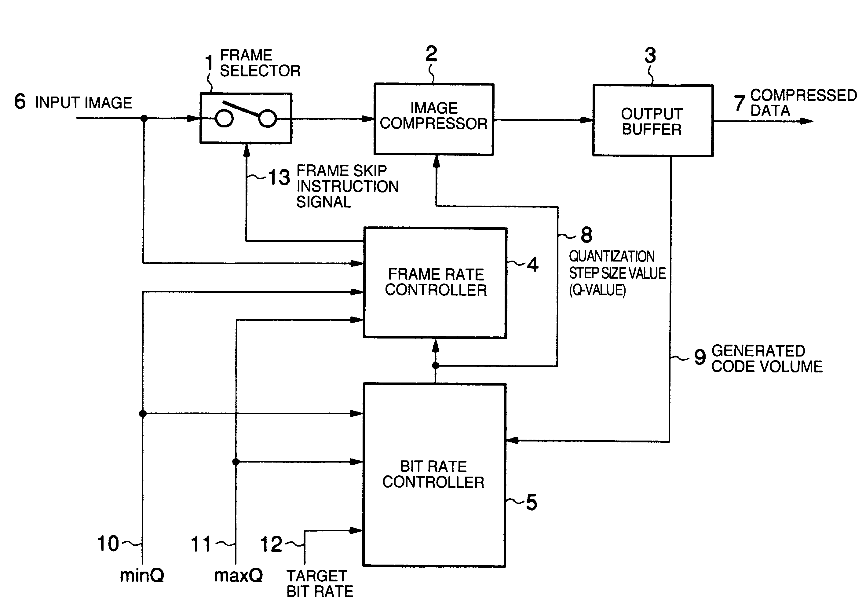
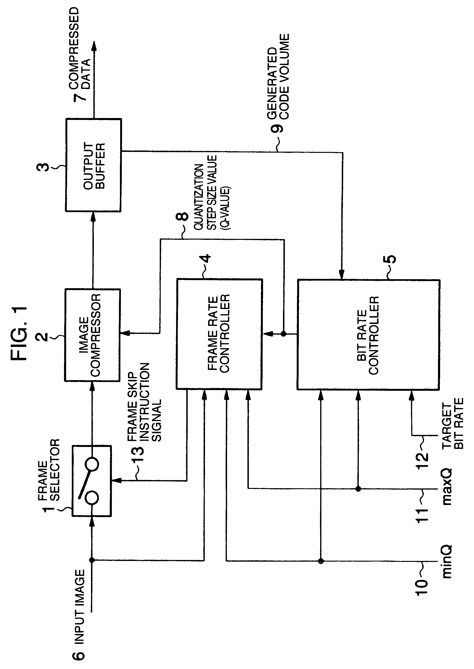
[0041]FIG. 1 shows a configuration example of the moving image compression apparatus according to an embodiment of the present invention.

[0042]The moving image compression apparatus shown in FIG. 1 includes a frame selector 1, an image compressor...


PUM


Abstract

There is provided an image data compression apparatus capable of effectively suppressing an image data volume after compression processing. A bit rate value is detected according to the image data volume after the compression processing. According to the bit rate size value detected, a quantization step size value used in the compression processing is modified. According to the quantization step size value, a skip frame number is set and a frame skip of the image data before or after the compression processing is performed according to the number of frame skip frames which has been set.

Description

INCORPORATION BY REFERENCE[0001]The present application claims priority from Japanese application JP2005-150779 filed on May 24, 2005, the content of which is hereby incorporated by reference into this application.BACKGROUND OF THE INVENTION[0002]The present invention relates to an apparatus and a method for compressing image data and in particular, to an image data compression apparatus and method capable of effectively suppressing an image data volume after the compression processing.[0003]In a conventional moving image compressing apparatus, control of a generated code volume has been performed by increase / decrease of a quantization step size value (hereinafter, referred to as a Q-value) inputted to an image compression unit and by a frame skip.[0004]It should be noted that the aforementioned conventional technique has been described, assuming that its inventor is already known but no appropriate document has been found and no conventional technique document information is descri...

Claims


Application Information

Patent Timeline
Patent Type & Authority Patents(United States)
IPC IPC(8): H04N7/12H04N11/02H04N19/00H03M7/30H04N19/126H04N19/132H04N19/136H04N19/146
CPCH04N19/172H04N19/152H04N19/132H04N19/124
Inventor KOTO, HARUHIRO
Owner KOKUSA ELECTRIC CO LTD
Why Eureka
Try Eureka