
RFID readers transmitting preambles denoting data rate and methods

a technology of preambles and data rates, applied in the field of radio frequency identification (rfid) readers, can solve the problems of rfid tags not being able to reliably detect the interrogating rf wave, the operation of rfid systems, and the inability of rfid tags to parse commands, etc., to achieve the effect of reducing the data rate of its transmission, reducing interference, and suitable data rates

Active Publication Date: 2011-07-05
IMPINJ
View PDF47 Cites 15 Cited by
  • Summary
  • Abstract
  • Description
  • Claims
  • Application Information

AI Technical Summary

Benefits of technology

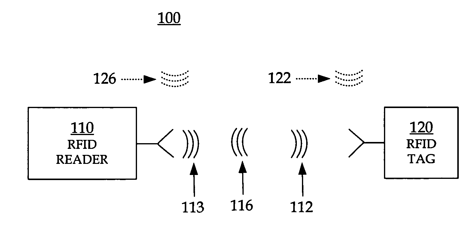
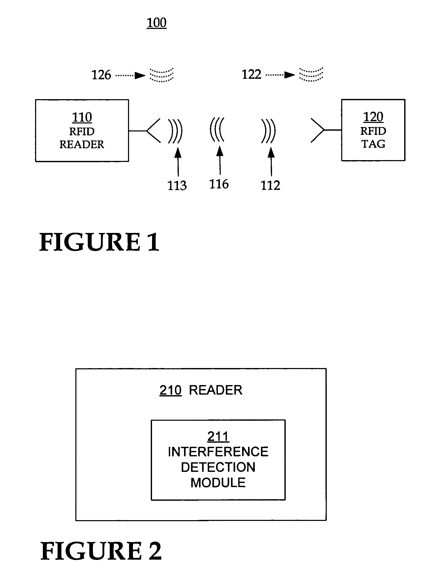
The invention provides RFID readers that can transmit data to query tags at different rates. Before transmitting the data, the RFID readers also transmit special preambles that inform of the data rate that will be used for transmitting the data. The preambles have a rate aspect that is determined by the data rate, and a call aspect that is implemented by call transitions that define a timing that is independent of the data rate. The invention can be used with RFID tags that have filters with different bandwidth settings. All tags can set their bandwidth at the same setting when waiting for a preamble, which may be chosen to be of the lowest bandwidth. The RFID reader can choose one of many data rates, which is especially useful when interference is detected and a more suitable data rate is attempted. This will allow any RFID tags that receive the transmission to better reject interference from the transmitted data and analyze it more robustly.

Problems solved by technology

A challenge in the operation of RFID systems arises when a tag or population of tags does not know what data rate will be used by the reader.
Another challenge in the operation of RFID systems arises from interference, when other RF signals are also transmitted in the vicinity at the same time.
In those instances, an RFID tag cannot detect the interrogating RF wave reliably, or parse its commands.

Method used


Image

  • RFID readers transmitting preambles denoting data rate and methods
  • RFID readers transmitting preambles denoting data rate and methods
  • RFID readers transmitting preambles denoting data rate and methods

Examples


Embodiment Construction

[0029]The present invention is now described. While it is disclosed in its preferred form, the specific embodiments of the invention as disclosed herein and illustrated in the drawings are not to be considered in a limiting sense. Rather, these embodiments are provided so that this disclosure will be thorough and complete, and will fully convey the scope of the invention to those skilled in the art. Indeed, it should be readily apparent in view of the present description that the invention may be modified in numerous ways. Among other things, the present invention may be embodied as devices, methods, software, and so on. Accordingly, the present invention may take the form of an entirely hardware embodiment, an entirely software embodiment or an embodiment combining software and hardware aspects. This description is, therefore, not to be taken in a limiting sense.

[0030]As has been mentioned, the present invention provides RFID readers that transmit data to query tags at one or more ...


PUM


Abstract

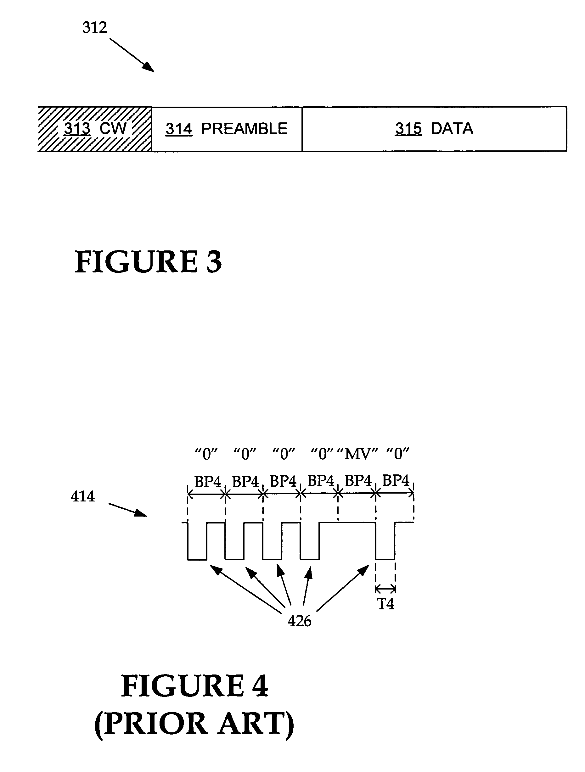
RFID readers transmit data to query tags at one or more data rates. Before transmitting data, the RFID readers also transmit special preambles that inform of the data rate that will be used for transmitting the data. The preambles have a call aspect and a rate aspect. The rate aspect has a feature substantially determined from a rate selected for transmitting the data. The feature may encode the rate indirectly or explicitly. The call aspect may be implemented by call transitions that define a timing, whose duration is independent of the selected rate. The duration may be advantageously set according to an assumed state of the RFID tag bandwidth filter. Therefore an RFID tag may use the call aspect of the preamble to prepare itself for receiving data, and the rate aspect to determine its rate of transmission for setting its filter bandwidth accordingly.

Description

RELATION TO OTHER APPLICATIONS[0001]This application claims benefit of U.S. Provisional Patent Application Ser. No. 60 / 570,247 filed May 11, 2004 in the name of inventors John D. Hyde and Christopher J. Diorio entitled “RFID Readers Transmitting Preambles For Data At Different Transmission Rates And Software And Methods” and being commonly assigned herewith. This application is also a continuation-in-part of co-pending U.S. patent application Ser. No. 10 / 823,991, filed Apr. 13, 2004 now U.S. Pat. No. 7,183,926 in the name of inventors Christopher J. Diorio, Scott Anthony Cooper, John D. Hyde, Amir Sarajedini and Kurt Eugene Sundstrom, entitled “Adaptable Bandwidth RFID Tags”, all commonly assigned herewith. This application may be found to be related to another U.S. patent application titled “RFID Readers Transmitting Preambles Denoting Communication Parameters And RFID Tags Interpreting The Same And Methods”, having attorney docket number IMPJ-0095, filed on the same day as the pre...

Claims


Application Information

Patent Timeline
Patent Type & Authority Patents(United States)
IPC IPC(8): H04Q5/22G06K7/00
CPCG06K7/0008G06K7/10297
Inventor HYDE, JOHN D.DIORIO, CHRISTOPHER J.
Owner IMPINJ
Learn More