Connection-oriented network node

a network node and network node technology, applied in the field of connection-oriented network nodes, can solve the problems of requiring enormous spare resources, affecting the operation, and both logical links suffering failures, and achieve the effect of efficient setting up a protection path and a monitoring path

Inactive Publication Date: 2011-07-12
FUJITSU LTD
View PDF17 Cites 8 Cited by
  • Summary
  • Abstract
  • Description
  • Claims
  • Application Information

AI Technical Summary

Benefits of technology

[0017]It is an object of the invention to provide a technology capable of efficiently setting up a protection path and a monitoring path.
[0048]According to the invention, it is possible to efficiently set up the protection path and the monitoring path for the working path.

Problems solved by technology

If the failure occurs, a failure detecting node promptly switches over the traffic on a working path passing the failure point to the protection path for rerouting the failure point.
Herein, if communication qualities (Quality of Service (QoS)) are considered about the network, it is required preparation of enormous spare resources.
Even when employing two different logical links in a certain network and when these links employ the same physical line, if a failure occurs in the physical line, both of the logical links suffer the failure.
The prior art using the SRLG described above includes a problem that the operation becomes complicated.

Method used


Image

  • Connection-oriented network node
  • Connection-oriented network node
  • Connection-oriented network node

Examples


operational example 1

[0126]Next, an operational example of the network system will be described. To begin with, an operational example 1 will exemplify how an originating node (PLR) of the protection path executes setup of the protection path (a case where the protection segment is explicitly designated).

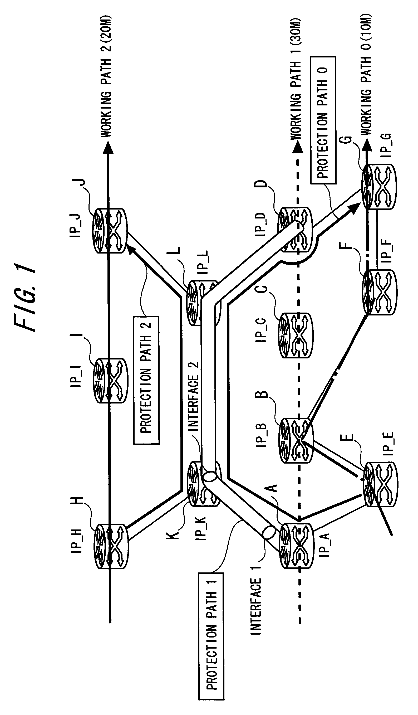
[0127]Herein, it is assumed that on the network illustrated in FIG. 1, a protection path 1 (A→K→L→D) protecting a segment (A→B→C→D) of a working path 1 is newly set. In the operational example 1, when setting up the protection path, the protection path is automatically associated with the working path. Further, a monitoring path for the working path is generated.

[0128]FIG. 5 is a sequence diagram showing a process of the originating node (the node A) of the protection path 1 in the operational example 1. When the protection path is set, a protection path generating command is inputted to the originating node of the protection path. Herein, the protection path generating command is inputted to the node A...

operational example 2

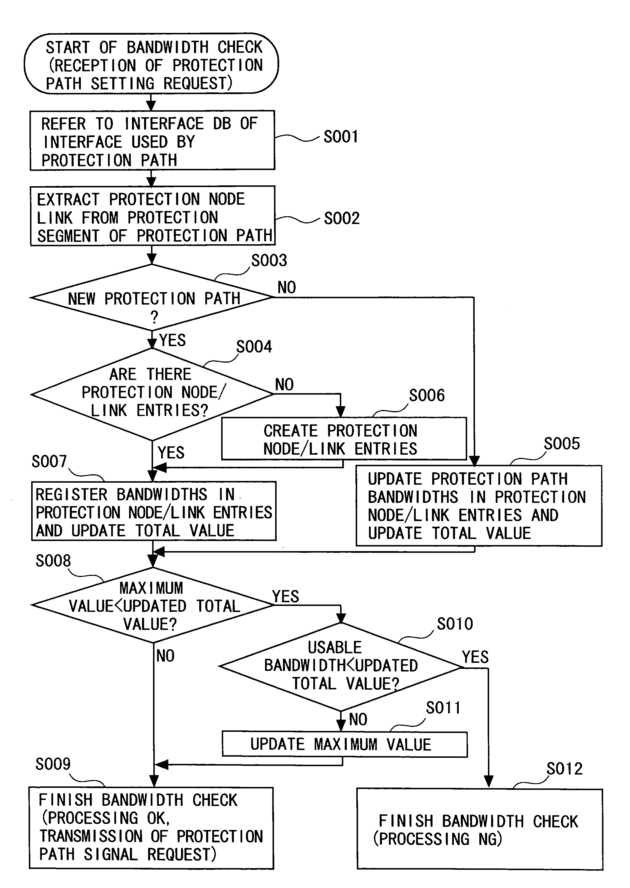
[0182]Next, a bandwidth check (an automatic bandwidth sharing computing process) in all nodes that the protection path passes, will be explained by way of an operational example 2

[0183]>

[0184]As a premise of the discussion on the operational example 2, signaling for establishing a path and forwarding of a data packet will be explained.

[0185]The protection path is, as stated above, set (established) by the signaling of the protection path from the originating point (head-end) node. In the first embodiment, LSP setup (MPLS TE-LSP setup) using RSVP (RFC3209) “RSVP-TE: Extensions to RSVP for LSP Tunnels” in MPLS Traffic Engineering (MPLS TE) for setting up a path (LSP) by an end-to-end scheme, is applied as the signaling for setting up the working path, the protection path and the monitoring path. Note that RSVP (Resource Reservation Protocol) as a basic protocol is defined in RFC2205.

[0186]In the MPLS TE-LSP setup, a PATH message defined as a path setup request message is sent from the...

operational example 3

[0210]Next, an operation of how the head-end node (PLR) of the protection path sets up the protection path in the case of designating none of the protection segment, will be explained by way of an operational example 3. Without even designating the protection segment when inputting a command to the head-end node, it is feasible to search for the protectable working path and to associate this working path with the protection path.

[0211]FIG. 15 is a sequence diagram showing an operation of the head-end node in relation to the setup of the protection path in the operational example 3. In FIG. 15, the same processes as those in the operational example 1 shown in FIG. 5 are marked with the same step numerals.

[0212]The operational example 3 is based on the assumption of a case of setting up, for instance, subsequently to the establishment of the protection path 1 explained in the operational examples 1 and 2, a new protection path 2 (route: nodes H→K→L→J) without designating the protectio...


PUM


Abstract

A connection-oriented network node capable of becoming an originating node of a protection path serving as a bypath of a protection segment included in a working path in a network system in which data is transferred via a path previously set up between nodes, comprises a usage bandwidth determining unit determining, when setting up the protection path, a usage bandwidth of the setup target protection path on the basis of a working path including the protection segment to be protected by the setup target protection path, and a generation unit generating, if a value obtained by adding the determined usage bandwidth to a current protection path usage bandwidth of an interface transmitting data that is forwarded on the setup target protection path, does not exceed a usable bandwidth for the protection path that is preset with respect to the interface, a signaling message for setting up the setup target protection path to send this message.

Description

BACKGROUND OF THE INVENTION[0001]1. Field of the Invention[0002]The invention relates to a connection-oriented network node. For example, the invention relates to a technology for rerouting a failure point while assuring a bandwidth when a failure occurs in a connection-oriented network such as a label forwarding network (MPLS (Multi-Protocol Label Switching)) for forwarding data in a way that attaches a label to a packet.[0003]2. Description of the Related Art[0004]A conventional method is exemplified such as Fast Rerouting (Internet Draft: draft-ietf-mpls-rsvp-lsp-fastreroute-07.txt) that is being examined by IETF (Internet Engineering Task Force). In this technology, a protection path rerouting the failure point is previously set up on the assumption of node / link failures. If the failure occurs, a failure detecting node promptly switches over the traffic on a working path passing the failure point to the protection path for rerouting the failure point. With this contrivance, the ...

Claims


Application Information

Patent Timeline
Patent Type & Authority Patents(United States)
IPC IPC(8): H04L12/26H04J3/14H04L12/28H04L45/24H04L45/247
CPCH04L45/10H04L45/22H04L45/28H04L45/50H04L67/1097H04L69/40
Inventor YAMADA, AKIKOODA, MASAYA
Owner FUJITSU LTD
Why Eureka
Try Eureka