Rotation planning apparatus and rotation planning system

a technology of rotating planning and planning apparatus, which is applied in the direction of programme control, total factory control, instruments, etc., can solve the problems of high workload of manual planning, particularly significant deterioration of parts, and the need for maintenance of parts, etc., to achieve less expensive, efficient planning, and more economical production activities

Active Publication Date: 2007-10-23
MITSUBISHI HITACHIPOWER SYST LTD
View PDF25 Cites 7 Cited by
  • Summary
  • Abstract
  • Description
  • Claims
  • Application Information

AI Technical Summary

Benefits of technology

[0009]For these reasons, a first object of the present invention is to provide the planning apparatuses or planning systems intended to efficiently set up plans for part usage rotation between a plurality of shafts or plants.
[0010]A second object of the present invention is to provide a rotation planning system by which a manufacturer or service provider who produces the parts of a plurality of plants and / or performs maintenance operations can not only implement planned production and manufacture by rapidly understanding the maintenance (including replacement and repair) plans relating to each plant, but also conduct more economical production activities and supply less expensive parts to the user.

Problems solved by technology

Also, parts of the types that suffer particularly significant deterioration require maintenance at fixed hours of operation, until the parts have reached the respective lives.
However, as described above, since the maintenance of the high-temperature parts used in gas turbines or the like needs to be planned considering the maintenance required at fixed periods, manual planning has been a task very high in workload.

Method used


Image

  • Rotation planning apparatus and rotation planning system
  • Rotation planning apparatus and rotation planning system
  • Rotation planning apparatus and rotation planning system

Examples


embodiment 1

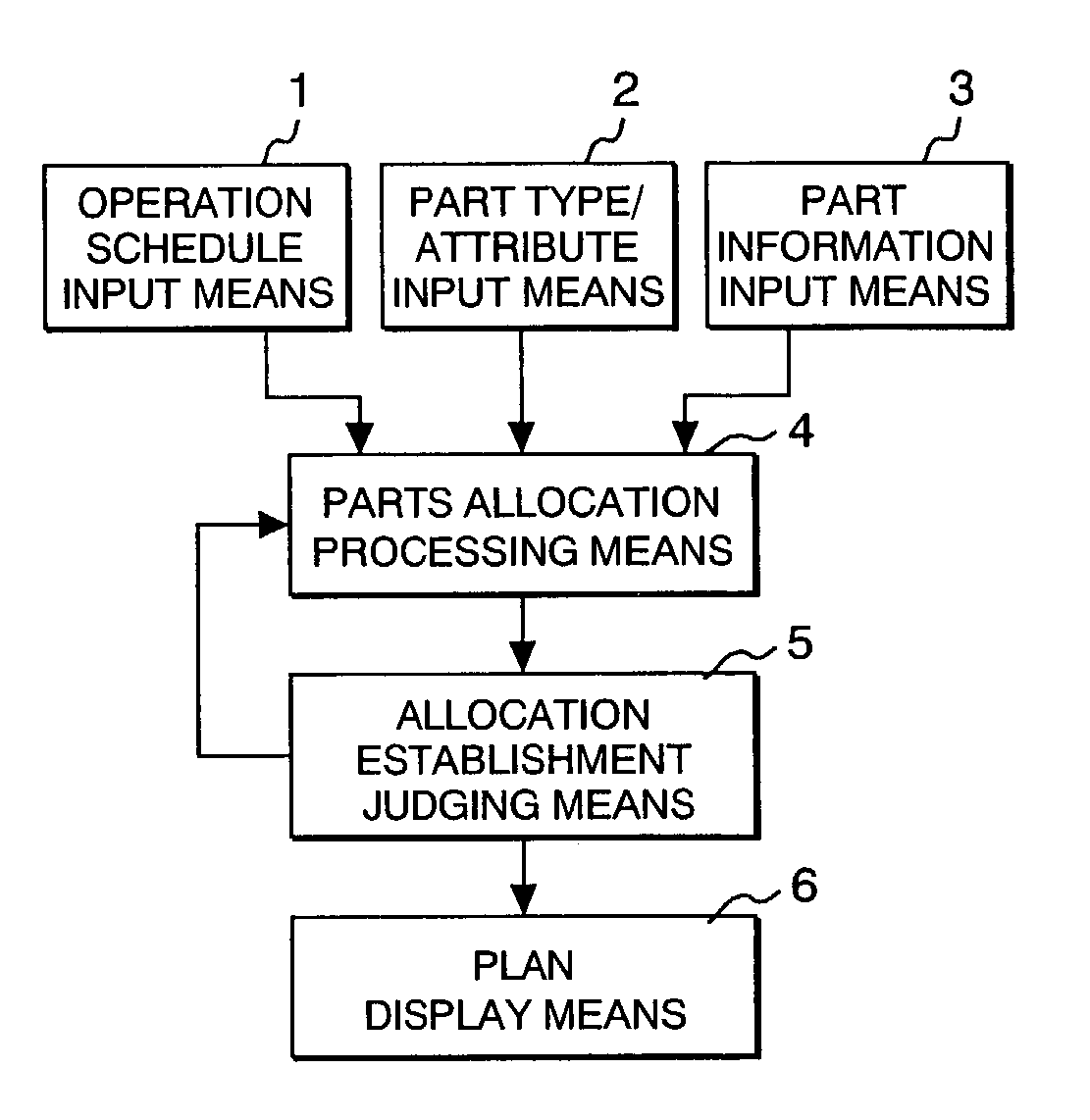
[0043]FIG. 1 is a block diagram showing the outline of the processes conducted by the rotation planning apparatus pertaining to the present embodiment. The rotation planning apparatus pertaining to the present embodiment conducts the processes by use of the plurality of means shown in FIG. 1. First, the present embodiment is outlined using FIG. 1.

[0044]The processes shown in FIG. 1 use at least an operation schedule input means 1, a part type / attribute input means 2, a part information input means 3, a part allocation processing means 4, an allocation establishment judging means 5, and a plan display means 6. Although, in the present application specification, each of these means is assigned a name for the convenience of description, as long as the processes outlined below are performed, the present invention is not limited by the names of the processing means. In the present embodiment, the operation schedule input means 1 accepts the input of the schedule information relating to t...

embodiment 2

[0088]Next, a second embodiment of the invention pertaining to the present application is described.

[0089]FIG. 9 is a block diagram showing the outline of the processes conducted by the rotation planning apparatus pertaining to the present embodiment. The block diagram of FIG. 9 shows the apparatus configuration having an evaluation function calculating means 7 added between the allocation establishment judging means 5 and plan display means 6 shown in the block diagram of FIG. 1.

[0090]The evaluation function calculating means 7 performs evaluation data calculations on the rotation plans that have been set up via part allocation processing means 4 and allocation establishment judging means 5. The use of the invention pertaining to the present application enables a plurality of part rotation plans to be established. When a plurality of plans are present, evaluation data for evaluating which plan is better is required. In evaluation function calculating means 7, therefore, evaluation ...

embodiment 3

[0102]Next, a third embodiment of the invention pertaining to the present application is described.

[0103]FIG. 12 is a block diagram showing the outline of a system which uses the rotation planning apparatus pertaining to the present embodiment. Numerals 122a, 122b, etc. in FIG. 12 each denote a plant for operating a single shaft or a plurality of shafts. Numeral 121 denotes a business site at which the actual operation results and operation plan information relating to the plants 122a, 122b, etc. are to be retained and management and maintenance plans are to be established. Plants 122a, 122b, etc. and the business site 121 are connected via a communications means 120 such as a telecommunications line, and data can be exchanged there.

[0104]Plants 122a, 122b, etc. are equipped with actual result / plan storage means 123a, 123b, etc., which are means of storing rotation plan information and actual results on each plant. These means are further equipped with data input / output means 124a, ...


PUM


Abstract

An apparatus or system is used for planning the rotation of part usage between shafts or plants based at least on schedule information relating to operation and inspection-purpose shutdown, attribute information relating to part life, part maintenance periods, and other part attributes, and part information relating to the parts to be used in the rotation.

Description

BACKGROUND OF THE INVENTION[0001]1. Field of the Invention[0002]The present invention relates to the planning apparatuses or planning-systems relating to the maintenance (including repair and replacement) of the parts used in gas turbines or the like.[0003]2. Prior Art[0004]The lives of the parts used in gas turbines or the like, especially, the lives of high-temperature parts, are determined, with the deterioration characteristics of the part materials taken into consideration, as the time over which the parts can withstand the operation of the gas turbines (that is to say, service life in the number of hours), and to operate the gas turbines over the time exceeding the lives of their parts, these parts need to be replaced with new ones. Also, parts of the types that suffer particularly significant deterioration require maintenance at fixed hours of operation, until the parts have reached the respective lives.[0005]In thermal plants, for example, a scheduled shutdown period for per...

Claims


Application Information

Patent Timeline
Patent Type & Authority Patents(United States)
IPC IPC(8): G06F17/40G06F7/00G06F19/00G06F7/76G05B19/418F01D5/00F01D25/00F02C7/00
CPCF01D5/005G06Q10/0631G06Q10/06311G06Q10/06G05B2219/32118G05B2219/32306F05D2230/80Y02P90/02Y02P90/80
Inventor HOTTA, MIYAKOKOJIMA, YOSHITAKAARAKI, KENJIMORITOMO, YOSHIKAZU
Owner MITSUBISHI HITACHIPOWER SYST LTD
Why Eureka
Try Eureka