Broadcasting receiving apparatus

Inactive Publication Date: 2008-08-28
FUNAI ELECTRIC CO LTD
View PDF2 Cites 0 Cited by
  • Summary
  • Abstract
  • Description
  • Claims
  • Application Information

AI Technical Summary

Benefits of technology

[0015]According to this structure, if it is decided that the antenna is a bidirectional antenna, the connected antenna is set in eight directions forming 22.5 degrees between neighboring directions between a prescribed direction and the direction forming 180 degrees with each other. If it is decided that the antenna is a unidirectional antenna, the connected antenna is set in sixteen directions forming 22.5 degrees between neighboring directions between a prescribed direction and the

Problems solved by technology

Such a directional antenna can receive even weak electric waves because of strong directivity, however, it has a drawback that it can receive only electric waves in a specific direction.
However, United States of America or the like has many areas where a plurality of transmission towers are distributed so as to surround an urban area, thus when a directional antenna is u

Method used


Image

  • Broadcasting receiving apparatus
  • Broadcasting receiving apparatus
  • Broadcasting receiving apparatus

Examples


Example

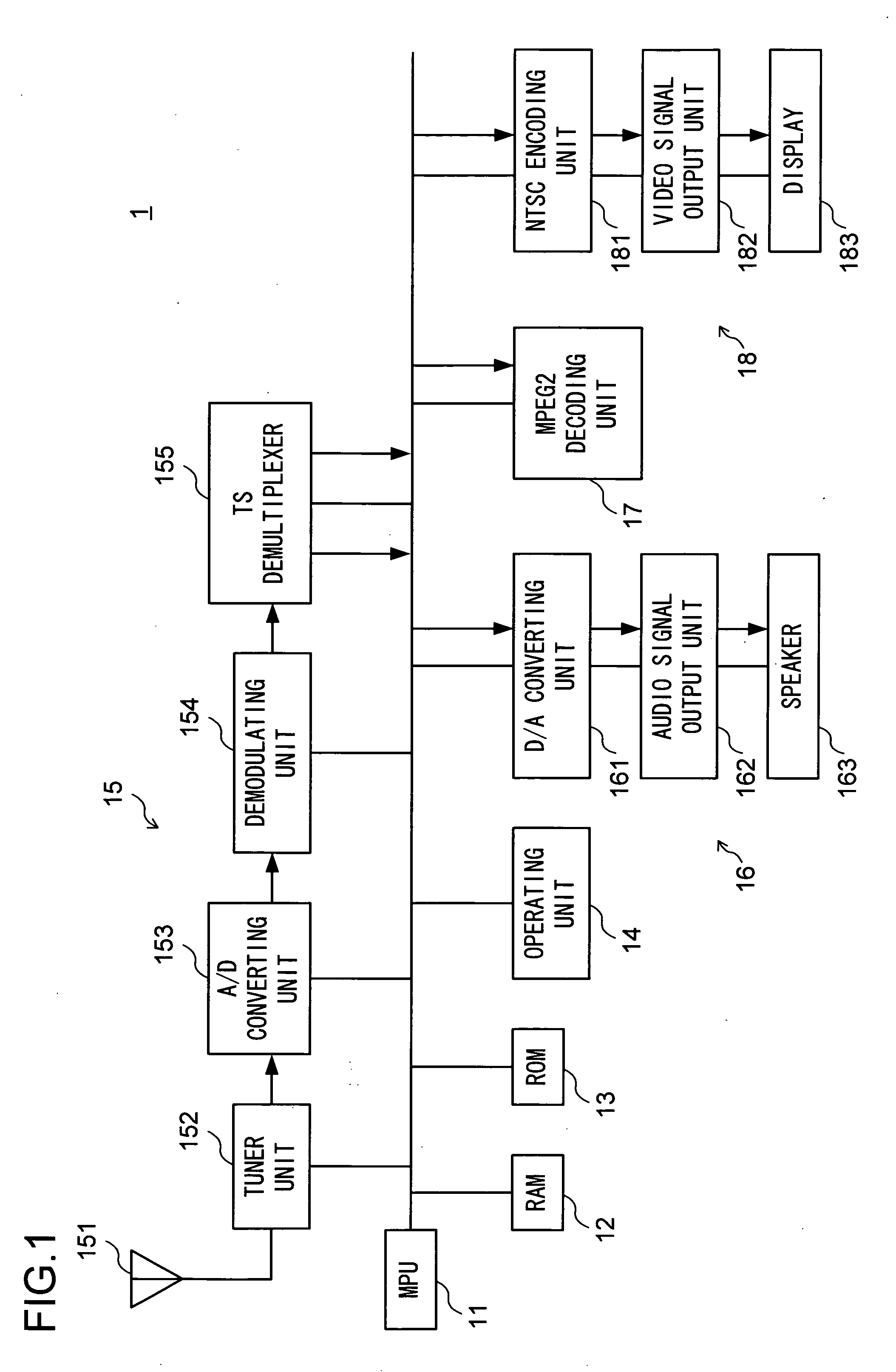
[0030]Hereinafter, an embodiment of the present invention will be described with reference to the attached drawings. FIG. 1 is a block diagram to show an example of the structure of a digital broadcasting receiving apparatus in accordance with the present invention. A digital broadcasting receiver 1 (corresponding to the broadcasting receiving apparatus) receives a television broadcast signal and delivers its content to a speaker 163 and a display 183 that will be described later. The digital broadcasting receiver 1 includes a micro processing unit (MPU) 11, random access memory (RAM) 12, read only memory (ROM) 13, an operating unit 14, a receiving unit 15, an sound output unit 16, an MPEG2 decoding unit 17, and an image output unit 18.

[0031]The MPU 11 controls the entire operation of the digital broadcasting receiver 1. The RAM 12 is a memory for storing information such as audio information, picture information and the like in a readable and rewritable manner. The ROM 13 is a memo...


PUM


Abstract

An MPU (11) of a digital broadcasting receiver has functional units that includes an antenna judging unit (115) for deciding whether an antenna connected to an antenna unit (151) is a bidirectional antenna having directivities in two directions forming substantially 180 degrees with each other or a unidirectional antenna having its directivity only in one direction, a second intensity obtaining unit (116) for setting the connected antenna in a plurality of prescribed directions between 0 degree and 180 degrees or between 0 degree and 360 degrees so that reception intensities are obtained for the individual setting directions if it is decided that the antenna is a bidirectional antenna or a unidirectional antenna, and a direction setting unit (117) for setting a direction of the connected antenna in the direction of the maximum reception intensity among the obtained reception intensities.

Description

[0001]This application is based on Japanese Patent Application No. 2007-031567 filed on Feb. 13, 2007, and the content of which are hereby incorporated by reference.BACKGROUND OF THE INVENTION[0002]1. Field of the Invention[0003]The present invention relates to a broadcasting receiving apparatus to which a smart antenna that is structured as an antenna changeable in directivity direction is connectable and which can receive television broadcast through the connected antenna and output the television broadcast onto a monitor.[0004]2. Description of Related Art[0005]A directional antenna such as Yagi antenna or the like has been hitherto used to receive television broadcast. Such a directional antenna can receive even weak electric waves because of strong directivity, however, it has a drawback that it can receive only electric waves in a specific direction. Such a characteristic causes little problem in Japan or the like where transmission towers for transmitting television broadcast...

Claims


Application Information

Patent Timeline
IPC IPC(8): G01R29/08
CPCH04N5/46H04N21/44209H04N21/42607
Inventor NARITA, SHUSUKE
Owner FUNAI ELECTRIC CO LTD
Why Eureka
Try Eureka